
The CAM software workflow is the bridge between a 3D design and a machined part. Understanding this workflow is essential for anyone who wants to go from a CAD model to cutting material on a CNC machine covered in our Fusion 360 CAM Tutorial. The CAM workflow follows a consistent sequence of steps regardless of which CAM software you use.
This guide covers the complete CAM workflow from importing the CAD model through generating the final G-code. I have organized it in the order you should follow for every programming job.
Importing the CAD Model
File Formats for Import
The first step in the CAM workflow is importing the 3D model into the CAM software. The model can be created in the CAM software if it has built-in CAD capabilities or imported from external CAD software. The most common file formats for CAM software import are STEP, IGES, and native CAD formats from major software packages.
STEP files are the most reliable and accurate format for transferring 3D models between different CAD and CAM software systems. STEP files preserve the exact geometry and do not lose precision during translation. Use STEP format whenever possible. IGES is an older transfer format that still works but may lose some surface definition in the translation process.
| Format | Best For | Reliability |
|---|---|---|
| STEP | 3D solids and surfaces | Highest |
| IGES | Legacy models | Moderate |
| STL | 3D printing, mesh models | Low |
| Native CAD | Same-software workflow | High |
Before importing, check that the model units match the CAM software unit setting. A model designed in millimeters that is imported as inches is scaled by 25.4 times which causes problems throughout the workflow. Verify the unit setting before importing.
Checking Model Quality
The quality of the 3D model directly affects the CAM workflow and toolpath reliability. A clean model with no gaps, overlaps, or surface defects produces reliable toolpaths. A dirty model with geometry errors causes toolpath calculation failures or incorrect paths. Inspect the 3D model for geometry defects before proceeding with the CAM workflow.
Setting Up the Stock
Defining Stock Dimensions
The stock is the raw material from which the part is machined. The stock can be defined as a rectangular block, a cylinder, or a custom shape that matches the raw material. The stock dimensions should be slightly larger than the part dimensions to allow for material removal.
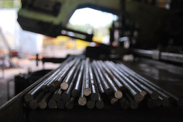
For rectangular stock define the width, length, and height dimensions in the CAM software. Add 0.05 to 0.1 inches of extra material on each side for roughing passes. For bar stock materials enter the actual diameter and length dimensions. The stock should be positioned relative to the part based on how it will actually be held in the machine.
Positioning the Stock
The stock position setting determines where the finished part is located within the raw material block. The part can be positioned at the center of the stock for symmetrical machining, at a corner for vise workholding, or at any other location that matches the actual setup on the machine. The CAM position must match the physical setup exactly for the program to cut in the correct location.
Here is a simple facing operation after post processing:
G90 G94 G17 G21 G54
M3 S5000
G0 X-0.25 Y-0.25 Z0.5
G1 Z-0.02 F20
G1 X4.25 F50
G0 Z0.5
M5 M30
This facing program assumes the stock is positioned with the top-left corner as the origin. Verify your stock position matches the programmed origin.
Defining the Coordinate System
Setting the Origin
The coordinate system in CAM defines the origin point for all toolpaths. The origin should match the work offset that will be used on the machine (typically G54). The most common origin location is the top center of the stock or a specific corner of the part.
The Z axis direction should point away from the machine table. The X and Y axes should align with the machine axes. Most setups use the top surface of the stock as Z zero. The origin point is typically at the center or corner of the stock.
Multiple Coordinate Systems
Multiple coordinate systems can be defined for parts that need machining from different orientations. Each orientation gets its own coordinate system with the origin at a convenient location for that setup. The CAM software assigns each toolpath to the appropriate coordinate system. This is especially useful for 3+2 machining where the part is machined from multiple angles in one setup.
Selecting Tools
Building a Tool Library
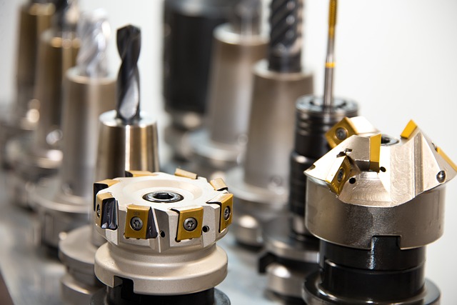
The tool selection step defines the cutting tools used in the program. Each tool must be defined with its diameter, flute length, overall length, shank diameter, and cutting parameters. The tool definition must match the actual tool that will be used in the machine.
The tool library stores tool definitions for reuse across multiple programs. Most CAM software comes with a default tool library that includes common tool sizes. You can add your own tools to the library with custom parameters. Building and maintaining a comprehensive tool library saves significant time on every CAM programming job.
Calculating Feeds and Speeds
The feeds and speeds for each cutting tool should be calculated based on the workpiece material and operation type. The CAM software may have a feed and speed database that provides starting values for common material combinations. Adjust the values based on your machine capability and experience. Start with conservative values and increase as you confirm the tool can handle the load.
Creating Toolpaths
Toolpaths are the paths that the cutting tool follows through the material to remove stock. The CAM software calculates the toolpath based on the selected geometry features, tool definition, and cutting parameters. Different toolpath strategies are used for different operations.
Roughing Toolpaths
Roughing toolpaths remove the bulk of the material quickly. They use larger depths of cut and higher feed rates than finishing paths. Adaptive roughing also called trochoidal roughing maintains a constant tool engagement angle which allows higher feed rates and longer tool life. This is the strategy I use for most aluminum roughing — it extends tool life significantly compared to traditional parallel passes.
Finishing Toolpaths
Finishing toolpaths produce the final surface finish and dimensions. They use lighter depths of cut and lower feed rates than roughing paths. The finishing pass removes the material left by the roughing pass typically 0.01 to 0.03 inches. A good finishing pass leaves a surface that requires minimal hand work.
Drilling Toolpaths
Drilling toolpaths create holes of various sizes in the part. They can be simple drilling for standard shallow holes or peck drilling for deep holes that need chip clearing. The drill cycle type is selected based on the hole requirements. Tapping and boring cycles are also available for threaded and precision holes.
Verifying Toolpaths
Running the Simulation
Toolpath verification is the process of simulating the tool movement to check for errors. The simulation shows the tool moving through the stock material and reveals potential collisions, uncut material, and toolpath errors before the program runs on the machine.
Simulation software shows the tool moving through the stock in real-time or at variable speed. Watch for tool collisions with the stock during simulation, excessive cuts that could overload the tool, and areas where the tool leaves uncut material behind. Pay special attention to tight corners where the tool engagement may exceed safe limits.
Collision Detection
Collision detection identifies potential collisions between the tool holder, spindle, and workpiece. The simulation should include the tool holder geometry for accurate collision checking. A collision in the simulation indicates a problem that must be fixed before running the program.
Post Processing
Post processing is the final step in the CAM workflow. The post processor converts the CAM toolpaths into G-code that the specific machine control can read. Each machine control has its own G-code dialect so the correct post processor must be selected.
The post processor applies the correct G-code format for the specific machine control. This includes the proper codes for spindle control, coolant activation, tool changes, and feed rate commands. The post processor also applies the correct decimal formatting, line numbering, and program header format for the target control.
Verify the posted G-code output before running the program on the machine. Check that the first few lines show the correct work offset, unit selection, and positioning mode. Look for any unexpected codes or missing safety lines.
CAM Workflow Best Practices
Organize your CAM programs with clearly separated operations for roughing and finishing passes. Use a consistent naming convention for operations so you can find and modify them easily.
Save your CAM program with the part file. This allows you to make changes later without recreating the entire program. The CAM program file stores all the setup information including stock definition, tool selection, and toolpaths.
Document your CAM settings for reference. Note the feeds, speeds, depths of cut, and tool selections for each operation. This documentation helps when setting up similar jobs in the future.
CAM for Different Machine Types
For 3-axis milling the workflow is straightforward with toolpaths in the XY plane and depth steps in Z. The stock setup defines a rectangular block and the toolpaths are 2D or 3D contours.
For 4-axis and 5-axis milling the CAM workflow includes the additional rotary axes. The toolpaths can be indexed 3+2 where the rotary axis positions the part and the tool cuts in 3-axis mode. Full simultaneous 5-axis toolpaths move all axes at the same time for complex surface machining.
For lathe turning the CAM workflow uses the XZ plane instead of XY. Turning operations include facing, rough turning, finish turning, grooving, threading, and parting off.
Multiaxis Toolpath Strategies
Swarf machining uses the side of the cutting tool to cut along a contoured surface. This produces a smooth finish on vertical walls and tapered surfaces. Swarf machining requires 5-axis capability.
Flank milling is similar to swarf machining but uses the full length of the tool for high material removal. The tool contacts the workpiece along its entire flute length.
Point milling uses the tip of the tool for finishing complex surfaces. The tool follows a path that maintains constant contact with the surface. Point milling produces the best surface finish but takes longer than other strategies.
Toolpath Optimization
Ramping entry reduces tool load by entering the material gradually rather than plunging straight down. This is gentler on the tool and produces better surface finish at the entry point.
Corner rounding slows the feed rate in sharp corners to maintain constant chip load. The CAM software can automatically reduce feed rate in corners based on the tool engagement angle. This prevents tool overload and breakage.
Linking moves connect different toolpath segments. Efficient linking reduces non-cutting time and improves cycle time.
CAM Program Organization
Organize the CAM program with a consistent structure to make it easier to edit and maintain. Group related operations together. Use descriptive names for each operation that indicate the operation type and the feature being machined.
Each operation should have a comment describing its purpose. Comments help other programmers understand the program intent and help when returning to a program months after it was created.
Use templates for common operation sequences. If you frequently machine similar parts create a template program with the operations already defined.
Troubleshooting CAM Problems
CAM problems often appear as errors during toolpath calculation or unexpected results in the simulation. The most common cause is incorrect geometry selection. Verify that the correct faces or contours are selected for each operation.
Toolpath calculation errors can be caused by geometry problems in the CAD model. Check the model for gaps, overlaps, or surface defects. A clean model produces reliable toolpaths.
Unexpected toolpath results are often caused by incorrect tool selection. Verify that the tool diameter, flute length, and overall length are correct. A tool that is too short cannot reach deep features. A tool that is too large leaves uncut material in corners.
The CAM workflow from 3D model to finished part follows a consistent sequence regardless of the software or machine type. Understanding each step helps you create reliable programs that machine correctly the first time. Take the time to set up each step properly and verify the results before moving to the next step. Rushing through the CAM workflow to save time usually results in more time spent fixing problems at the machine.
The CAM workflow is a skill that develops with practice. Each part you program teaches you something new about toolpath strategies, material behavior, and machine capabilities. Start with simple 2D parts and work up to complex 3D surfacing and multi-axis work as your skills develop.
For more CAM guides see our Fusion 360 CAM Tutorial and our G-Code for Beginners guide.
 CNC Conversational Programming Guide: A Beginner's IntroductionJune 27, 2026 · Tutorials
 Fusion 360 CAM Tutorial for Beginners: From Design to G-CodeJune 27, 2026 · Tutorials
 What is CNC Machining? A Complete Beginner's GuideJune 25, 2026 · Tutorials
 CNC Basics for Beginners: A Complete Guide to Getting StartedJune 25, 2026 · Tutorials