CNC machining has its own language. When you are starting out terms like chipload, work offset, climb milling, and canned cycle can sound like a foreign language. This glossary defines over 50 essential CNC terms that every machinist should know. I have grouped them by category so you can find what you need quickly.
G-Code and Programming Terms
| Category | Example | Purpose |
|---|---|---|
| Type A | Example 1 | Purpose 1 |
| Type B | Example 2 | Purpose 2 |
| Type C | Example 3 | Purpose 3 |
Absolute positioning (G90): A mode where all coordinates are measured from the part zero point. G90 X1 Y1 moves the tool to a position one inch from part zero in each axis. This is the default mode for most CNC programs.
Incremental positioning (G91): A mode where coordinates are measured from the current tool position rather than from part zero. G91 X1 moves the tool one inch in the positive X direction from wherever the tool currently is.
Canned cycle: A G-code that performs a multi-step machining operation with a single command. G81 is a drilling canned cycle that positions the tool, feeds to depth, and retracts automatically. G84 is a tapping canned cycle.
Modal command: A G-code that stays active until another command in the same group changes it. G00 stays in effect for all subsequent moves until G01, G02, or G03 is called. This is why you do not need to repeat G00 before every rapid move.
Work offset (G54-G59): A coordinate shift that tells the machine where the part is located on the table. Six standard registers let you set up multiple parts and switch between them mid-program.
Tool length offset (H code): A Z-axis compensation value that accounts for different tool lengths. Each tool gets a unique H value and G43 H1 activates the offset for tool 1.
Cutter compensation (G40-G42): An automatic adjustment of the tool path to account for the tool diameter. G41 offsets the tool to the left of the programmed profile and G42 offsets to the right.
Dwell (G04): A pause in program execution for a specified time. G04 P1.0 pauses for 1 second. Used at the bottom of a drill cycle to improve hole finish or to clear chips.
R plane: The retract height in canned cycles. The tool rapids to this height before feeding to depth. Must be set above the workpiece surface.
Peck drilling (G83): A drilling cycle that retracts the tool periodically to clear chips. Used for holes deeper than about three times the drill diameter.
Rigid tapping (G84): A tapping cycle where the spindle feeds synchronously with the Z-axis to cut threads without a floating tap holder.
Boring cycle (G85): A boring cycle that feeds into the hole and feeds back out at the same rate for finishing bored holes to tight tolerances.
Subprogram (M98/M99): A separate program called from within the main program using M98. M99 returns control to the main program. Subprograms reduce code duplication for repeated operations.
Coordinate system: The reference framework for all positions in a CNC program. Machine coordinates use the machine home position. Work coordinates use the part zero position.
Fixture offset: Another term for work offset. The coordinate shift that locates the part on the machine table relative to machine home.
Rapid move (G00): The fastest possible movement of the machine axes. Used for positioning only not for cutting. Each axis moves at its maximum speed independently.
Linear move (G01): A controlled feed rate movement along a straight line. Used for all cutting moves. The tool moves at the programmed feed rate.
Circular move (G02/G03): A controlled movement along an arc or circle. G02 moves clockwise and G03 moves counterclockwise.
Block: A single line of G-code. Each block typically contains one or more commands. The control executes blocks sequentially.
Block delete (/): A feature that skips lines starting with a slash when block delete mode is active. Used to skip optional operations like coolant on or off.
Tool call (T code): A command that selects a tool for use. T1 selects tool 1 from the tool magazine. The tool change happens when T code is followed by M06.
Spindle speed (S code): A command that sets the spindle speed in RPM. S5000 sets the spindle to 5,000 RPM. Used with M03 for forward rotation.
Feed rate (F code): A command that sets the feed rate in inches per minute or millimeters per minute. F10 sets a feed rate of 10 IPM.
Machining Terms
Speeds and feeds: Speeds refer to spindle rotation speed in RPM or SFM. Feeds refer to the rate of tool movement through the material in IPM or MMPR. Together they determine cutting performance.
Chipload (IPT): The thickness of material each cutting tooth removes. The single most important parameter in machining. Measured in inches per tooth or IPT.
SFM (Surface Feet per Minute): The linear speed at which the cutting edge moves through the material. Determines spindle RPM based on tool diameter.
MRR (Material Removal Rate): The volume of material removed per minute calculated as depth of cut times width of cut times feed rate.
Climb milling: The tool rotates in the same direction as the feed. Produces better surface finish and longer tool life but requires a rigid machine with no backlash.
Conventional milling: The tool rotates against the feed direction. Produces more heat and wear but is safer on machines with backlash in the lead screws.
Stepover: The radial engagement of the tool expressed as a percentage of tool diameter. Light stepovers produce better finish while heavy stepovers maximize material removal.
Depth of cut: The axial engagement of the tool into the material measured in the Z direction.
Chip thinning: When radial stepover is below 50 percent of tool diameter the actual chip becomes thinner than the programmed chipload requiring a feed rate increase.
Built-up edge (BUE): Material that welds to the cutting edge during machining. Common in aluminum when cutting without coolant. Ruins surface finish.
Chatter: Self-excited vibration during machining caused by lack of rigidity. Produces a characteristic wavy surface finish and loud noise.
Tooling Terms
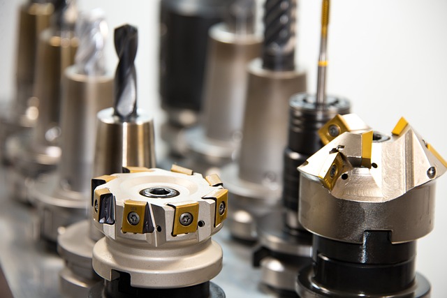
End mill: A rotating cutting tool with cutting edges on both the end and sides. Used for milling operations including slotting, profiling, and contouring.
Ball nose end mill: An end mill with a full radius tip used for 3D contouring and mold work. Produces a scalloped surface finish on flat floors.
Corner radius end mill: A flat end mill with a small radius at the corner. Combines flat floor capability with stronger cutting edges that resist chipping.
Roughing end mill: An end mill with serrated cutting edges for aggressive material removal. Leaves a rough surface finish requiring a finishing pass.
Flute: The helical groove on an end mill that evacuates chips from the cutting zone. More flutes mean higher feed rates but less chip clearance.
Helix angle: The angle of the flute relative to the tool axis. High helix angles improve chip evacuation. Low helix angles strengthen the cutting edge.
Collet: A precision clamping device that holds the cutting tool in the spindle. ER collets are the most common type for CNC machines.
Runout (TIR): The deviation of the cutting edge from true rotation measured with a dial indicator. High runout degrades surface finish and tool life.
Carbide: A hard cutting tool material made from tungsten carbide particles in a cobalt binder. Three times harder than HSS.
HSS (High-Speed Steel): A tough cutting tool material that bends before breaking. Cheaper than carbide but wears faster in abrasive materials.
Machine Terms
VMC (Vertical Machining Center): A CNC mill with a vertical spindle orientation. The most common type of CNC milling machine in job shops.
HMC (Horizontal Machining Center): A CNC mill with a horizontal spindle. Provides better chip evacuation and higher productivity than VMCs.
ATC (Automatic Tool Changer): A mechanism that swaps tools automatically during machining without operator intervention.
Pallet changer: A system that exchanges workpieces automatically allowing one part to be machined while another is being set up.
Servo motor: A motor with position feedback for precise motion control. Standard on all industrial CNC machines.
Stepper motor: A motor that moves in discrete steps without position feedback. Common on hobby CNC machines.
Ball screw: A precision leadscrew with recirculating balls for low-friction, high-precision linear motion.
Linear guide: A precision rail and bearing system for low-friction axis movement.
Gantry: A bridge-style machine frame where the tool moves on an overhead beam. Common on CNC routers.
Spindle: The precision electric motor that holds and rotates the cutting tool. The heart of every CNC machine.
VFD (Variable Frequency Drive): An electronic drive that controls the speed of an AC induction spindle motor by varying the input frequency.
Encoder: A feedback device that reports the actual position or speed of a motor or axis to the control. Essential for closed-loop servo systems.
Limit switch: A sensor that detects when an axis has reached the end of its allowed travel. Triggers an emergency stop to prevent mechanical damage.
Home switch: A sensor that establishes the machine zero reference position for each axis. Found during the homing cycle at machine startup.
Coolant through spindle (CTS): A system that delivers coolant through the center of the spindle and tool directly to the cutting edge. Improves tool life in deep hole drilling.
Probe: A precision touch sensor used to measure part position, tool length, and workpiece dimensions automatically on the machine.
Tool setter: A device used to measure tool length and diameter automatically. Can be mounted on the table or in the tool changer.
Work light: An LED or fluorescent light mounted inside the machine enclosure to illuminate the work area.
Chip shield: A transparent window or door that protects the operator from flying chips and coolant.
Door interlock: A safety switch that stops the machine when the operator door is opened. Prevents access to moving parts.
Air blast: A stream of compressed air directed at the cutting zone to clear chips and cool the tool. Cheaper alternative to coolant for some operations.
Operation Terms
Tramming: Adjusting the spindle to be perfectly perpendicular to the machine table surface. Essential for accurate machining.
Surfacing: Cutting a thin layer from the wasteboard or workpiece to create a flat reference surface.
Dry run: Running a CNC program without cutting material to verify the tool path. Catches most crashes before they happen.
Single block: A mode that executes one line of G-code at a time. Used for program verification.
Lights-out machining: Running a CNC machine unattended. Requires reliable workholding and tool monitoring.
First article inspection: Measuring the first part produced to verify it meets specifications.
Zero return: Moving all machine axes to their home switch positions to establish a known reference point.
Fixture offset: Another name for work offset. The coordinate shift that locates the part on the machine table.
Backlash: The amount of lost motion in a mechanical system when direction changes. Caused by clearance between screw threads and nuts. Common on older machines.
Way cover: Protective covers that shield machine guideways from chips and coolant. Must be maintained to prevent debris from damaging precision surfaces.
Chip conveyor: An automated system that removes chips from the machining area and deposits them in a collection bin. Essential for lights-out operation.
Coolant: A fluid used to cool the cutting zone and lubricate the cutting edge. Also flushes chips away from the tool. Common types include flood coolant, mist coolant, and through-spindle coolant.
Coolant concentration: The ratio of coolant concentrate to water. Typically 5 to 10 percent for general machining. Measured with a refractometer.
Drawbar: The mechanism in a spindle that holds the tool holder by pulling it into the spindle taper. Activated by hydraulic pressure or a spring and released by air pressure.
Tool magazine: The storage location for tools in an automatic tool changer. Can hold between 10 and 200 tools depending on the machine size.
Chip load: Another term for chipload. The material thickness each cutting tooth removes per revolution.
Ramp angle: The angle at which a tool enters material when using helical ramp entry. Typically 1 to 5 degrees for end mills.
Stepover: The radial distance between adjacent tool paths in a pocket or surface operation. Tighter stepovers produce better surface finish.
Scallop height: The height of the cusp left between adjacent ball nose tool paths. Determined by stepover distance and tool radius.
Finish allowance: The amount of material left for the finishing pass after roughing. Typically 0.005 to 0.030 inch.
Roughing pass: An initial machining pass that removes the bulk of material quickly. Leaves a rough surface for finishing.
Finishing pass: A final light machining pass that achieves the required surface finish and tolerance.
Plunge: A vertical feed movement where the tool enters the material axially. End mills should not plunge at the same rate as side cutting.
Ramp entry: A method of entering material where the tool moves simultaneously in X, Y, and Z along a helical or linear path.
For more foundational knowledge see our [CNC Basics for Beginners](
G90 G54 G00 X0 Y0
G01 Z-0.1 F10
G01 X1.0 F20
M30
/posts/cnc-basics-for-beginners/) guide and our Complete G-Code List reference.
 CNC Machining Tolerances Guide: ISO 2768 Standards and Practical FitsJune 27, 2026 · Reference
 What is CNC Machining? A Complete Beginner's GuideJune 25, 2026 · Tutorials
 CNC Basics for Beginners: A Complete Guide to Getting StartedJune 25, 2026 · Tutorials
 Complete G-Code List: CNC Programming Reference with ExamplesJune 25, 2026 · Reference