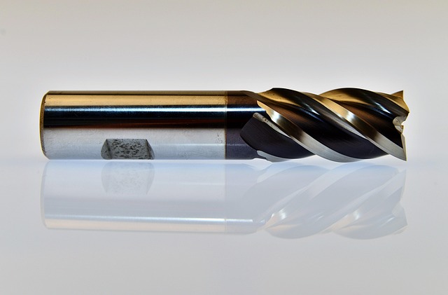
Feeds and Speeds for Beginners: CNC Cutting Parameters Guide
Feeds and speeds are the two most important cutting parameters in CNC machining. Spindle speed (S) controls how fast the tool rotates. Feed rate (F) controls how fast the tool moves through the material. Getting these values right is the difference between a clean, accurate part and a broken tool or scrapped workpiece. This guide explains how feeds and speeds work, how to calculate them, and gives you reference tables for common materials.
flowchart TD
    A[Surface Speed SFM] --> B{Calculate RPM}
    B -->|RPM = SFM × 3.82 ÷ Tool Ø| C[RPM = S]
    C --> D{Calculate Feed Rate}
    D -->|Feed = RPM × Chip Load × Flutes| E[Feed Rate = F]
    E --> F{Set Depth of Cut}
    F -->|Start 0.5× tool Ø| G[Run Test Cut]
    G --> H{Check chips?}
    H -->|Too small| I[↑ Speed or ↓ Feed]
    H -->|Too large| J[↓ Speed or ↑ Feed]
    H -->|Clean curls| K[✅ Optimal]
What Are Feeds and Speeds
| Term | What It Is | Code | Units |
|---|---|---|---|
| Spindle speed | How fast the tool rotates | S3000 | RPM |
| Feed rate | How fast the tool moves through material | F200 | mm/min |
| Depth of cut | How much material removed per pass | Z moves | mm |
| Stepover | Width of cut radial engagement | Toolpath | percent of tool diameter |
The relationship between these values determines the chip load — the thickness of material each cutting edge removes per revolution. Correct chip load produces clean chips, good surface finish, and reasonable tool life. Incorrect chip load causes poor surface finish, premature tool wear, tool breakage, or burned material.
The RPM Formula
RPM is calculated from the material cutting speed and tool diameter:
RPM = (SFM x 318) / Tool Diameter (mm)SFM stands for Surface Feet per Minute — the speed at which the cutting edge passes through the material. Higher SFM produces faster material removal but generates more heat.
Starting SFM by Material
| Material | SFM Range (Carbide) |
|---|---|
| Aluminum 6061 | 600-1500 |
| Mild steel | 200-400 |
| Stainless steel 304 | 150-300 |
| Tool steel | 100-250 |
| Brass | 600-1200 |
| Copper | 200-400 |
| Wood | 2000-4000 |
| Acrylic | 500-1000 |
| MDF | 2000-4000 |
The Feed Rate Formula
Feed Rate (mm/min) = RPM x Number of Flutes x Chip Load (mm/tooth)Chip load is the thickness of material each cutting edge removes. A higher chip load removes material faster but increases cutting forces and tool wear.
Starting Chip Load by Material (6mm End Mill)
| Material | Chip Load mm/tooth |
|---|---|
| Aluminum | 0.02-0.05 |
| Steel | 0.01-0.03 |
| Stainless | 0.008-0.02 |
| Brass | 0.03-0.08 |
| Wood | 0.05-0.15 |
| Acrylic | 0.03-0.08 |
| MDF | 0.05-0.15 |
Quick Reference Table (6mm Carbide End Mill)
| Material | RPM | Feed mm/min | DOC mm | Stepover |
|---|---|---|---|---|
| Aluminum | 10000 | 600 | 0.5-1.0 | 30-40% |
| Mild steel | 4000 | 240 | 0.2-0.5 | 20-30% |
| Stainless | 3000 | 120 | 0.1-0.3 | 15-20% |
| Brass | 12000 | 1200 | 0.5-1.5 | 30-50% |
| Wood | 15000 | 2000 | 1.0-3.0 | 40-60% |
| Acrylic | 8000 | 800 | 0.5-1.0 | 30-40% |
| MDF | 16000 | 2500 | 1.0-3.0 | 40-60% |
How to Read the Cut
The sound and appearance of the cut tell you whether your parameters are correct. Listen to the machine and look at the chips being produced.
| Symptom | Likely Cause | Fix |
|---|---|---|
| Smooth sound, clean chips | Parameters correct | No change needed |
| Squealing or high pitch | Speed too high or feed too slow | Reduce RPM or increase feed |
| Chattering vibration | Feed too fast or DOC too deep | Reduce feed or DOC |
| Burning or discoloration | Speed too high or feed too slow | Reduce RPM or increase feed |
| Tool breaks | Feed too fast, DOC too deep, or RPM too slow | Reduce feed and DOC |
| Poor surface finish | Feed too fast for RPM | Reduce feed or increase RPM |
When you hear the cut sounding smooth and consistent, the parameters are in the right range. Adjust from there based on the surface finish and tool wear you observe.
Depth of Cut and Stepover
| Operation | DOC (6mm tool) | Stepover |
|---|---|---|
| Roughing | 1.0-2.0mm | 40-50% |
| Finishing | 0.2-0.5mm | 5-10% |
Roughing removes material quickly with deeper cuts and larger stepovers. Finishing achieves the final surface finish and dimensional accuracy with lighter cuts. Always leave at least 0.2-0.3mm of material for the finishing pass.
Material-Specific Guidelines
Aluminum
Aluminum is one of the most forgiving materials for CNC beginners. Use coolant or WD-40 as lubricant to prevent material from sticking to the cutting edges. Climb milling produces better surface finish than conventional milling. Two-flute end mills designed specifically for aluminum give the best results. Aluminum 6061 is the most common alloy for hobby machining. (See our CNC End Mill Selection Guide for tool recommendations.)
Steel
Steel requires a rigid machine and carbide tooling to cut successfully. Use flood coolant to control heat at the cutting interface. Take light passes of 0.2-0.5mm depth of cut with a 6mm end mill. Coated carbide tools with TiAlN or AlTiN coatings last significantly longer than uncoated tools in steel.
Stainless Steel
Stainless steel is difficult to machine because it work-hardens. Use sharp coated carbide tools and maintain a consistent feed rate — letting the tool dwell in one spot causes work hardening that damages both the tool and the part. Use light depths of cut and higher feed rates to stay under the work-hardening threshold.
Plastics
Heat is the main challenge when machining plastics. Too much heat causes the material to melt and recast onto the cutting tool, ruining the surface finish. Use coolant if possible or reduce spindle speed to manage heat generation. Sharp cutting tools are essential — dull tools rub rather than cut, generating excessive heat.
Wood and MDF
Wood and MDF cut easily but produce fine dust particles that are harmful to breathe. Always use dust collection and wear a respirator when machining these materials. Carbide cutting tools stay sharp much longer than high-speed steel in wood. Use compression spiral bits for clean cuts on both the top and bottom edges of sheet material.
Using Feeds and Speeds Calculators
Manual calculation is useful for understanding the formulas but dedicated calculators save time and reduce errors. Free options include:
| Calculator | Platform | Features |
|---|---|---|
| FSWizard | iOS, Android | Material database, tool library, machine correction factors |
| G-Wizard Editor | Windows | Full-featured with stepover optimization |
| Walter Speed | Web | Professional grade, manufacturer data |
| Sandvik Coromant | Web | Industry standard, comprehensive database |
These calculators account for dozens of variables including tool material, coating type, workpiece material hardness, machine rigidity, and operation type. They provide more accurate starting parameters than manual calculation.
Adjusting Parameters for Your Machine
The reference tables in this guide assume a rigid machine in good condition. If your machine is a hobby-grade desktop router with an aluminum frame, reduce the recommended feed rates by 30-50 percent to compensate for lower rigidity. If your machine is a industrial VMC with a cast iron frame, you can increase feed rates by 20-30 percent.
The best approach is to start with conservative settings and increase the feed rate gradually until the cut sounds right. A feed rate that is too slow is safe but produces poor surface finish. A feed rate that is too fast breaks tools and damages the part. Start slow and increase until you find the sweet spot.
What’s Next?
Understanding Chip Formation
The chips produced during cutting tell you whether your feeds and speeds are correct. Good chips are a sign of good parameters. Bad chips mean something needs adjustment.
Correct chips are small, curled, and consistent in shape. For aluminum, correct chips look like tiny commas. For steel, they are thin, curled strands. For plastics, they are fine, powdery particles.
Incorrect chips include long stringy chips that wrap around the tool (feed too high or chip breaker needed), powdery dust instead of chips (feed too low, tool rubbing instead of cutting), discolored blue or brown chips (too much heat from excessive speed), and chips that are welded or smeared onto the tool (inadequate coolant or incorrect coating).
If you see any of these incorrect chip patterns, stop and adjust your parameters before continuing.
Calculating Speeds and Feeds Step by Step
Here is the complete process for calculating feeds and speeds from scratch for a new job:
- Determine the material you are cutting and find its SFM range from the table above
- Measure the tool diameter with calipers
- Calculate RPM using the formula: RPM = (SFM x 318) / Tool Diameter
- Select a chip load from the table based on material and operation type
- Calculate feed rate: Feed = RPM x Number of Flutes x Chip Load
- Set depth of cut based on operation (roughing or finishing)
- Run a test cut and adjust based on chip appearance and cutting sound
Example calculation for cutting aluminum with a 6mm two-flute end mill:
- SFM for aluminum: 800 (mid-range)
- RPM = (800 x 318) / 6 = 42,400 RPM
- Maximum spindle speed is 24,000 RPM, so use 24,000 RPM and adjust SFM accordingly
- Actual SFM at 24,000 RPM = (24000 x 6) / 318 = 453 SFM
- Chip load for aluminum finishing: 0.03 mm/tooth
- Feed rate = 24000 x 2 x 0.03 = 1440 mm/min
- Starting depth of cut: 0.5mm for finishing
This calculation gives you a safe starting point. Adjust from there based on the sound and finish quality.
The Relationship Between Feed Rate and Surface Finish
The surface finish produced by a flat end mill is directly related to the feed rate and spindle speed. The theoretical surface finish can be calculated as:
Scallop height = Feed Rate^2 / (4 x Tool Diameter x RPM^2)
This formula shows that reducing the feed rate by half improves the surface finish by a factor of four. Increasing RPM also improves finish but generates more heat. For the best surface finish use a low feed rate, moderate RPM, and light depth of cut for the final finishing pass.
Tool Wear Management
Cutting tools wear out over time. Using a dull tool produces poor surface finish and requires more power from the spindle. Monitoring tool wear helps you replace tools at the right time.
Signs of a worn tool include: increased cutting noise, visible wear on the cutting edges under magnification, higher power draw on the spindle load meter, and declining surface finish quality.
Tool life depends on cutting parameters, material, and coolant use. Typical tool life for carbide end mills in aluminum is 30-60 minutes of cutting time. In steel, 15-30 minutes. In stainless, 10-20 minutes. Replace tools before they fail catastrophically to avoid scrapping parts.
Common Feeds and Speeds Mistakes
Using the same feed rate for roughing and finishing. Roughing removes material quickly with deeper cuts and higher feed rates. Finishing requires lighter cuts and lower feed rates for good surface finish. Using roughing parameters for finishing produces a rough surface. Using finishing parameters for roughing takes too long and may cause tool deflection.
Not accounting for tool runout. Tool runout causes one flute to cut more material than the others, reducing effective tool life and surface finish quality. Measure runout with a dial indicator and keep it under 0.02mm for best results.
Ignoring machine rigidity. A hobby CNC router with an aluminum frame cannot cut at the same feeds and speeds as a industrial VMC with a cast iron frame. Reduce calculated parameters by 30-50 percent for less rigid machines.
Running at maximum RPM unnecessarily. Higher RPM generates more heat and reduces tool life. Use the lowest RPM that achieves the required surface finish to extend tool life and reduce heat generation.
Not adjusting for tool wear. As the tool wears, cutting forces increase. If surface finish degrades or cutting sound changes, the tool is worn and needs replacement.
Optimizing Material Removal Rate
Material removal rate (MRR) measures how much material you remove per minute. Higher MRR means faster cycle times but higher cutting forces and more heat.
MRR = DOC x Stepover x Feed Rate
For roughing, maximize MRR within the limits of your machine and tool. For finishing, reduce MRR to achieve the required surface finish and dimensional accuracy. The balance between roughing and finishing parameters determines the overall cycle time and the quality of the finished part. Finding the right balance for each job is part of the skill of CNC machining.
When to Use Coolant
Coolant extends tool life and improves surface finish by removing heat and lubricating the cutting interface. Use flood coolant for steel and stainless steel. Use mist coolant or WD-40 for aluminum. Use air blast for plastics to prevent melting. Dry cutting is acceptable for wood, MDF, and cast iron.
Coolant also helps with chip evacuation. Chips that are not cleared from the cutting zone can be recut, damaging the tool and worsening surface finish. Ensure the coolant nozzle is aimed directly at the cutting interface.
Building Your Own Feeds and Speeds Database
The best feeds and speeds data comes from your own experience with your specific machine and tools. Keep a notebook or spreadsheet with the parameters you use for each material and tool combination. Include the RPM, feed rate, depth of cut, stepover, and notes about the surface finish and tool wear you observed.
Over time this database becomes more useful than any generic reference table because it accounts for the specific characteristics of your machine, your tool holders, and your workholding methods.
Start with the reference tables in this guide, record the results on your specific machine, and refine the parameters based on your observations over time. What works on one machine may need adjustment on another.
Getting feeds and speeds right is a skill that develops with practice. Every time you try a new material or tool combination you add to your experience. The reference tables give you a starting point. Your own observations refine it from there.
Understanding feeds and speeds is essential for successful CNC machining. The formulas and reference tables in this guide give you a reliable starting point for any material and tool combination you are likely to encounter as a beginner.
Practice applying these formulas to different material and tool combinations. The more you use them, the more intuitive they become.
Each job you run adds to your knowledge. Use the formulas and trust your ears.
 CNC Machine Setup: Complete Guide from Power-On to First CutJune 26, 2026 · Guides
 CNC End Mill Selection Guide: Types, Coatings, Flutes, and MaterialsJune 22, 2026 · Guides
 CNC Feeds and Speeds: A Beginner's Guide to Optimal ParametersJune 20, 2026 · Guides