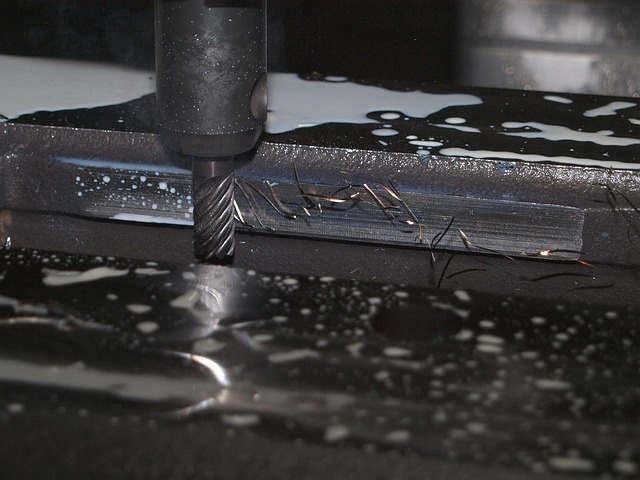
How Does a CNC Machine Work? The Simple Explanation
A CNC machine works by following programmed instructions (G-code) to move a cutting tool along precise paths and remove material from a workpiece. The machine reads a list of coordinates and commands from a program file, executes them one by one from top to bottom, and shapes the material into the finished part. The entire process is automated — once the program starts, the machine operates without human intervention.
The Three Core Systems
Every CNC machine, regardless of size or cost, has three essential systems that work together.
1. The Control System (The Brain)
The control system reads the G-code program and converts each line into electrical signals that move the machine. It consists of:
- A controller board (such as GRBL on Arduino, Mach3, or a Fanuc industrial controller)
- Firmware that interprets G-code commands
- Software that sends the program to the controller
- Driver boards that power the motors
When you press Cycle Start, the controller reads the first line of G-code, determines which axes need to move and how far, and sends the appropriate signals to the motor drivers.
2. The Drive System (The Muscles)
The drive system moves the machine axes in response to signals from the controller. It consists of:
- Stepper motors or servo motors that provide rotational motion
- Leadscrews or ballscrews that convert rotation to linear motion
- Linear guides that keep the movement straight
- Couplers that connect the motor to the leadscrew
Each axis has its own motor and leadscrew. When the controller sends a signal to move the X axis 10mm, the X motor rotates the correct amount, the leadscrew turns, and the axis moves exactly 10mm.
3. The Cutting System (The Hands)
The cutting system removes material from the workpiece. It consists of:
- The spindle motor that rotates the cutting tool
- The collet or chuck that holds the tool
- The cutting tool itself (end mill, drill, or other tool)
The spindle rotates at speeds from 1000 RPM (for large tools in steel) to 24000 RPM (for small tools in wood or plastic). The speed is controlled by the S-word in the G-code program.
How the Three Systems Work Together
When a CNC program runs, the three systems work in sequence:
- The controller reads a line of G-code
- It calculates the required motion
- It sends signals to the motor drivers
- The motors rotate the leadscrews
- The axes move to the target position
- The spinning tool cuts the material
- The controller reads the next line and repeats
This cycle repeats hundreds or thousands of times per minute, with each cycle moving the tool incrementally along the programmed toolpath.
The CNC Workflow: From Design to Part
Before the machine can cut anything, a program must be created. The workflow has four steps:
Step 1: Design in CAD Software
You design the part using CAD (Computer-Aided Design) software. The software creates a 3D model of the part with all dimensions and features defined.
Step 2: Generate Toolpaths in CAM Software
CAM (Computer-Aided Manufacturing) software takes the 3D model and calculates the toolpaths needed to cut it. The CAM software decides which tools to use, what speeds to run them at, and what path they should follow.
Step 3: Post-Processing to G-Code
The CAM software generates toolpaths in a generic format. A post-processor converts these into G-code that your specific machine controller can understand.
Step 4: Machining
You transfer the G-code to the machine, set up the material, set the work offset, and run the program. The machine executes the program automatically.
Axis Movement Explained
CNC machines move along axes:
- X-axis: Left and right movement
- Y-axis: Front and back movement
- Z-axis: Up and down movement
Each axis is driven by a motor connected to a leadscrew. When the motor rotates, the leadscrew turns and the axis moves linearly. The distance moved is proportional to the number of motor rotations.
How Stepper Motors Work
Stepper motors are the most common type of motor on hobby CNC machines. They move in discrete steps — typically 200 steps per revolution. The controller sends a pulse for each step, and the motor rotates by 1.8 degrees per pulse.
By counting pulses, the controller knows exactly how far the motor has rotated. By knowing the leadscrew pitch, it calculates how far the axis has moved. This open-loop control system works reliably as long as the motor has enough torque to move the axis without losing steps.
G-Code Execution Cycle
The controller executes each G-code line through this sequence:
- Read the line from the program
- Parse it into individual words (G01, X100, F200, etc.)
- Validate each word for allowed values
- Calculate the target position for each axis
- Plan the acceleration and deceleration profile
- Send step pulses to the motor drivers
- Monitor for limit switches or emergency stop
- Read the next line and repeat
What’s Next?
- [CNC Basics for Beginners](
G90 G54 G00 X0 Y0
G01 Z-0.05 F10
G01 X1.0 F20
G0 Z0.5
M30
/posts/cnc-basics-for-beginners/)
Machine Coordinate Systems
Every CNC machine has a built-in coordinate system that defines where the tool is at all times. Two coordinate systems are used:
Machine coordinates are the absolute position of the tool relative to the machine home position. This is set by the manufacturer and cannot be changed. Machine coordinates are accessed using G53.
Work coordinates are the position of the tool relative to the part zero point. The part zero is set by the operator using work offsets (G54-G59). All G-code program coordinates are in the work coordinate system.
The difference between machine and work coordinates is the offset value. When you set G54 X0 Y0 Z0 at a specific physical position on the table, the controller remembers the machine coordinate values at that position and subtracts them from all following coordinates.
Types of CNC Machines
CNC Mill
A CNC mill uses a rotating cutting tool that moves along X, Y, and Z axes to remove material from a stationary workpiece. The tool spins at high speed while the machine moves it along the programmed toolpath.
CNC Lathe
A CNC lathe spins the workpiece while a stationary cutting tool moves along it. The workpiece is held in a chuck and rotates at high speed. The cutting tool moves parallel and perpendicular to the axis of rotation.
CNC Router
A CNC router is similar to a mill but designed for larger work areas and softer materials. Routers have higher spindle speeds and less rigid frames than mills.
Machine Components in Detail
The Spindle
The spindle is the motor that rotates the cutting tool. It is the heart of the cutting system. Spindles are rated by:
- Maximum RPM (revolutions per minute)
- Power output (watts or horsepower)
- Collet size (ER11, ER16, ER20, etc.)
- Cooling method (air-cooled or water-cooled)
Higher RPM allows the use of smaller tools. Higher power allows deeper cuts in harder materials. The collet size determines the maximum tool shank diameter.
Linear Motion Components
The axes move on linear guides or rails that provide smooth, precise motion. The quality of the linear guides directly affects the machine precision.
Linear rails use recirculating ball bearings for low-friction motion. They are used on industrial machines and higher-end hobby machines.
V-slot wheels use bearing wheels running in aluminum extrusions. They are common on hobby routers.
Rod and bushing systems use linear bearings on hardened steel shafts. They are found on budget machines.
Leadscrews and Ballscrews
Leadscrews convert rotational motion from the motor to linear motion of the axis. They are rated by:
- Pitch (distance moved per revolution)
- Diameter
- Material and hardness
- Backlash (play between screw and nut)
Ballscrews use recirculating ball bearings between the screw and nut for zero-backlash motion. They are used on industrial machines.
Lead screws use a threaded shaft with a brass or plastic nut. They have measurable backlash but are much cheaper than ballscrews.
Machine Precision Factors
Several factors determine how precisely a CNC machine cuts:
| Factor | Impact on Precision |
|---|---|
| Frame rigidity | High — flex reduces accuracy |
| Linear guide quality | High — play causes errors |
| Leadscrew quality | High — backlash affects positioning |
| Motor resolution | Medium — steps per mm |
| Controller processing | Low — modern controllers are fast enough |
| Temperature stability | Medium — thermal expansion affects large parts |
A rigid frame with quality linear guides and ballscrews produces the most accurate parts.
CNC Machine Sizes
CNC machines range from desktop to industrial:
| Category | Typical Work Area | Typical Cost |
|---|---|---|
| Desktop hobby | 300 x 200mm | $300-$3000 |
| Benchtop | 600 x 400mm | $3000-$10000 |
| Industrial VMC | 1000 x 500mm | $50000-$500000 |
| Gantry router | 2000 x 1000mm | $10000-$100000 |
Choosing the right size machine depends on the size of parts you need to make.
Machine Tuning and Calibration
A CNC machine needs periodic calibration to maintain accuracy:
Steps per mm calibration adjusts how many motor steps are needed to move one millimeter. This is set in the controller configuration and affects all dimensions.
Backlash compensation adjusts for play in the leadscrew nut. The controller adds extra distance when changing direction to compensate.
Spindle tramming adjusts the spindle so it is perfectly perpendicular to the table. An untrammed spindle produces angled cuts.
Axis squareness ensures the X and Y axes are at 90 degrees. A machine with axes out of square produces parallelogram-shaped parts.
Regular calibration keeps the machine producing accurate parts.
How Coolant Systems Work
Coolant serves three purposes in CNC machining: cooling the cutting interface, lubricating the cut, and flushing chips away from the work area.
Flood coolant delivers a steady stream of liquid to the cutting area. It is the most common cooling method and is used for most metal cutting operations.
Mist coolant sprays a fine mixture of coolant and air. It is used when flood coolant would be excessive or when visibility of the cut is important.
Air blast uses compressed air to clear chips and cool the tool. It is used for plastics and materials that cannot tolerate liquid coolant.
Coolant is controlled by M-codes: M08 turns flood on, M07 turns mist on, M09 turns all coolant off.
How Tool Changers Work
Many CNC machines have automatic tool changers (ATC) that swap tools without operator intervention. The ATC stores tools in a magazine or carousel. When the program calls M06 T2, the machine moves to the tool change position, the current tool returns to the magazine, tool 2 is selected, and the machine resumes operation.
ATC systems save significant time in production because tool changes take 5-10 seconds instead of the 30-60 seconds needed for manual changes.
Machine Safety Systems
CNC machines include multiple safety systems to protect both the operator and the machine:
Emergency stop — a large red button that instantly stops all motion when pressed. Every CNC machine has at least one emergency stop within easy reach.
Limit switches — sensors at the ends of each axis travel that stop motion if the axis reaches its maximum permitted travel. They prevent the machine from over-traveling and damaging itself.
Door interlocks — switches that stop the spindle and axes when the machine door is opened. They prevent the operator from reaching into the machine while it is running.
Torque limiting — some controllers monitor motor torque and stop if the load exceeds a threshold, indicating a crash or broken tool.
How CNC Differs from Manual Machining
In manual machining, the operator turns handwheels to move the cutting tool. The operator controls the feed rate, depth of cut, and toolpath manually. This requires constant attention and skill.
In CNC machining, the program controls all movements. Once the program is running, the operator monitors the machine but does not directly control the cutting. This allows one operator to run multiple machines and produces consistent results across multiple parts.
Machine Communication
The CNC controller communicates with the computer through various interfaces:
USB — common on hobby machines. Simple and widely supported. Parallel port — older standard, still used on some industrial machines. Ethernet — increasingly common on modern controllers for faster data transfer. RS-232 serial — older industrial standard, still found on legacy equipment.
Wireless connections are possible but not recommended for production work due to potential communication drops.
Machine Power Requirements
CNC machines vary significantly in power requirements:
| Machine Type | Voltage | Current |
|---|---|---|
| Desktop hobby router | 110-220V | 5-10A |
| Benchtop mill | 220V | 15-20A |
| Industrial VMC | 220-480V | 30-100A |
| Large gantry router | 220V | 20-50A |
Always check the power requirements of your machine before connecting it to ensure you have adequate electrical service.
How CNC Machines Are Built
A CNC machine frame must be rigid enough to resist cutting forces without flexing. Common frame materials include:
Cast iron — used on industrial machines. Excellent vibration damping and rigidity. Heavy and expensive.
Steel weldments — welded steel frames. Good rigidity at lower cost than cast iron. Common on mid-range machines.
Aluminum extrusion — T-slot aluminum framing. Common on hobby routers. Lower rigidity but easy to assemble and modify.
Aluminum plate — machined from solid aluminum plate. Good for small machines where rigidity requirements are lower.
The frame material and design are the primary factors determining a machine cutting capability. A cast iron frame can cut steel aggressively. An aluminum extrusion frame requires light cuts in softer materials.
Understanding Machine Specifications
When comparing CNC machines, these specifications tell you the most about capability:
Work area (travel) — the maximum distance each axis can move. Determines the maximum part size.
Positioning accuracy — how precisely the machine can position the tool. Typically 0.01-0.05mm for hobby machines and 0.002-0.01mm for industrial machines.
Repeatability — how precisely the machine returns to the same position. Usually about half the positioning accuracy.
Maximum feed rate — how fast the axes can move. Higher feed rates reduce cycle times.
Spindle power and speed range — determines what materials can be cut efficiently.
Understanding these machine specifications helps you compare different machines objectively and choose the right one for your specific cutting requirements and budget.
A CNC machine is a complex system of mechanical, electrical, and software components working together. Understanding how each component contributes to the overall function of the machine helps you operate it more effectively. Use this knowledge as you learn to program and operate your machine.. Understanding how your machine works is the foundation for successful CNC operation.
 What is CNC Machining? A Complete Beginner's GuideJune 25, 2026 · Tutorials
 CNC Basics for Beginners: A Complete Guide to Getting StartedJune 25, 2026 · Tutorials
 Difference Between G-Code and M-Code in CNC Programming ExplainedJune 27, 2026 · Tutorials