
A CNC machine does not care what you want to make. It follows the instructions you give it. Your job is to give it the right instructions.
This tutorial walks you through machining your first CNC part — a simple aluminum mounting bracket — from start to finish. You will design it in Fusion 360, generate toolpaths, set up the machine, and cut the part. By the end you will have completed the entire CNC workflow and understand what each step does.
The part we are making is a 3“ × 2“ × 0.5“ aluminum bracket with a pocket and two through-holes. It is simple enough to finish in one session but complex enough to teach facing, contouring, pocketing, and drilling.
What You Will Need
| Item | Specification | Notes |
|---|---|---|
| CNC machine | Mill or router with at least 4“ × 4“ work area | Tormach, Shapeoko, Onefinity, or similar |
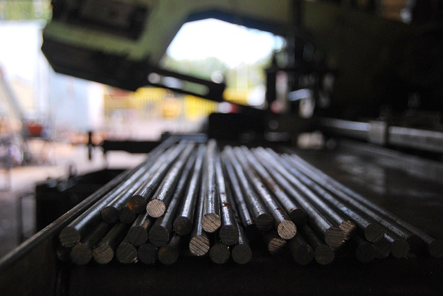
| Material | 6061 aluminum, 3“ × 2“ × 0.5“ | Available at Online Metals, McMaster, or local supplier |
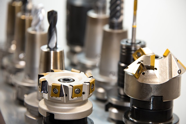
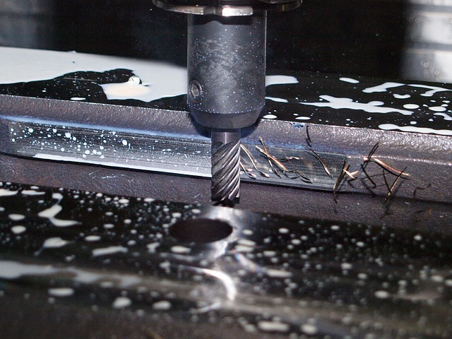
| End mill 1 | 1/4“ 2-flute uncoated carbide | For facing, contouring, and pocketing |
| End mill 2 | 1/8“ 2-flute carbide | For smaller features if needed |
| Drill bit | #7 drill bit (0.201“) | For 1/4-20 tapped holes |
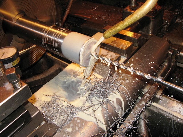
| Coolant | Mist coolant or WD-40 | Prevents chip welding |
| Workholding | Vise or clamps | Must hold the 3“ × 2“ × 0.5“ blank securely |
| Software | Fusion 360 (free hobbyist license) | CAD + CAM in one package |
Step 1: Design the Part in CAD
Open Fusion 360 and create a new design. The part is a flat plate with a pocket and two holes.
Create the Base Plate
- Create a new sketch on the top plane
- Draw a rectangle centered on the origin: 3“ wide × 2“ tall
- Finish the sketch
- Extrude the rectangle 0.5“ upward — this is the base plate
Add the Pocket
- Create a new sketch on the top face of the plate
- Draw a rectangle: 2“ wide × 1“ tall, centered on the plate
- Offset the rectangle inward by **0.25“ — this creates the pocket walls
- The pocket dimensions are: **1.5“ × 0.5“
- Finish the sketch
- Extrude the pocket 0.25“ downward (remove material)
Add the Mounting Holes
- Create a new sketch on the top face
- Draw two circles: 0.201“ diameter (#7 drill)
- Position them 0.25“ from each edge in opposite corners
- Finish the sketch
- Extrude the holes through all (remove material, 0.5“ deep)
Save the Design
Save the Fusion 360 design as first-bracket v1. You now have a complete 3D model ready for CAM.
Step 2: Generate Toolpaths in CAM
Switch to the Manufacture workspace in Fusion 360. This is where you tell the software how to cut the part.
Setup
- Select your machine type from the post-processor list (e.g., Haas, Tormach, GRBL)
- Define the stock as the same size as your material: **3“ × 2“ × 0.5“
- Set the stock box origin to the top center of the part (this becomes your G54 zero)
Operation 1: Face the Top
| Parameter | Value |
|---|---|
| Operation | Face |
| Tool | 1/4“ 2-flute carbide end mill |
| Spindle speed | 10,000 RPM |
| Feed rate | 50 IPM |
| Stepover | 50% of tool diameter |
| Depth per pass | 0.010“ |
| Stock to leave | 0.000“ |
This faces the top surface flat. Even if the material is already flat, facing ensures the top is parallel to the machine table.
Operation 2: Rough the Pocket
| Parameter | Value |
|---|---|
| Operation | 2D Pocket |
| Tool | 1/4“ 2-flute carbide end mill |
| Spindle speed | 10,000 RPM |
| Feed rate | 40 IPM |
| Stepover | 40% of tool diameter |
| Maximum roughing stepdown | 0.050“ |
| Stock to leave | 0.010“ (for finishing) |
Operation 3: Finish the Pocket Walls
| Parameter | Value |
|---|---|
| Operation | 2D Contour (finish pass) |
| Tool | 1/4“ 2-flute carbide end mill |
| Spindle speed | 10,000 RPM |
| Feed rate | 30 IPM |
| Stock to leave | 0.000“ |
This cleans up the 0.010“ left by the roughing pass, producing a smooth wall surface.
Operation 4: Drill the Holes
| Parameter | Value |
|---|---|
| Operation | Drilling (G81 cycle) |
| Tool | #7 drill bit (0.201“) |
| Spindle speed | 4,000 RPM |
| Feed rate | 8 IPM |
| Depth | Through all (0.5“ + drill tip) |
| Cycle | G81 (standard drilling) |
Simulate Before Generating G-Code
Click Simulate in Fusion 360 CAM. Watch the toolpath from start to finish. Verify:
- The tool does not crash into the vise or clamps
- The pocket is machined to the correct depth
- Both holes are drilled completely through
- The facing pass covers the entire top surface
Common CAM Mistakes to Avoid
| Mistake | Consequence | How to Avoid |
|---|---|---|
| Wrong post-processor selected | G-code does not work on your machine | Double-check the post matches your controller |
| Stock box larger than material | Tool rapids through air, wasting time | Set stock box to exact material dimensions |
| Tool diameter wrong in CAM | Pocket comes out undersized or oversized | Measure each tool and enter exact diameter |
| No stock to leave on roughing | Finishing pass has nothing to clean up | Leave 0.005-0.010“ for finishing |
| Feed rate too conservative | Tool rubs instead of cutting | Use recommended starting feeds |
| Work offset mismatch | Machine cuts in wrong location | Verify G54 in CAM matches G54 on machine |
Step 3: Post-Process and Load G-Code
- Select the correct post-processor for your machine
- Click Post to generate the G-code file
- Save the file as
first-bracket.ncorfirst-bracket.txt - Transfer the file to your CNC machine via USB, network, or SD card
What the G-Code Looks Like
The first few lines of your program should look something like this:
%
O1000 (FIRST BRACKET)
(T1 = 1/4 END MILL)
(T2 = #7 DRILL)
G90 G94 G17 G54  (Safety block: absolute, IPM, XY plane, G54)
T1 M06           (Load tool 1)
S10000 M03       (Spindle on at 10,000 RPM)
G00 X1.5 Y1.0    (Rapid to start position)
G43 Z1.0 H1      (Tool length offset, move to clearance)
Z0.1             (Approach)
G01 Z0 F20.      (Feed to top surface)
...              (Toolpath continues)
Verify that the G-code calls G54 (the work offset you will set on the machine) and that the tool numbers match the tools you have loaded.
Step 4: Set Up the Machine
Follow the setup procedure from the CNC Machine Setup Guide:
- Home the machine — Z first, then X, then Y
- Load tools — Tool 1 (1/4“ end mill) and Tool 2 (#7 drill bit)
- Set tool length offsets — touch off each tool and record the offset
- Mount the workpiece — clamp the 3“ × 2“ × 0.5“ aluminum blank securely in a vise
- Set G54 part zero:
- Z zero = top of the material
- X zero = center of the part (left-right)
- Y zero = center of the part (front-back)
- Load the G-code program
- Dry run — raise Z by 2“, run the program with spindle off, watch for clearance
Step 5: Make the First Cut
| Setting | Value |
|---|---|
| Rapid override | 25% |
| Feed override | 50% |
| Single block | ON |
| Hand position | On Feed Hold |
Press Cycle Start. Watch the first 10 seconds carefully. The tool should:
- Move to the start position at reduced rapid speed
- Lower to the clearance plane above the part
- Start the facing pass across the top surface
Listen for: A smooth, consistent cutting sound. You should see chips forming — not dust. If you hear squealing (tool rubbing), increase the feed override. If you hear chatter, decrease the feed override.
During the pocket roughing: The tool will make multiple passes, each 0.050“ deeper. This is normal. The cut should sound consistent throughout each pass.
During drilling: The drill will feed into the material in one continuous motion (G81 cycle). It will retract after reaching full depth. Both holes should be identical.
Step 6: Inspect and Measure
After the program finishes, stop the machine and remove the part.
What to Check
| Feature | Expected | How to Measure |
|---|---|---|
| Overall width | 3.000“ | Calipers |
| Overall height | 2.000“ | Calipers |
| Thickness | 0.500“ | Calipers |
| Pocket depth | 0.250“ | Depth micrometer or caliper depth rod |
| Pocket width | 1.500“ | Inside calipers |
| Hole diameter | 0.201“ | Drill gauge or pin gauge |
| Surface finish | Smooth, no visible tool marks | Visual inspection |
Common First-Part Issues
| Issue | Likely Cause | Fix Next Time |
|---|---|---|
| Pocket is shallow | Z zero was set incorrectly | Re-touch Z zero with the paper method |
| Holes are not through | Drill depth was wrong | Extend drill depth past material thickness |
| Rough surface finish | Feed rate too low or tool dull | Increase feed or replace end mill |
| Burrs on edges | Tool is cutting instead of shearing | Use climb milling for final pass |
| Part shifted during cut | Clamping was insufficient | Tighten vise or add more clamps |
Step 7: Finish and Deburing
- Remove burrs from all edges with a deburring tool or file
- Clean the part with alcohol or degreaser to remove coolant residue
- Inspect the final dimensions — if everything is within 0.010“ of the target, call it a success
- Tap the holes (optional): If you have a 1/4-20 tap, thread both holes
Summary: The Complete Workflow
CAD (15 min)     →  CAM (15 min)    →  Post (2 min)
  Design part        Generate            Create G-code
  in Fusion 360      toolpaths

Setup (10 min)   →  Dry Run (3 min)  →  Cut (20 min)
  Home, load tools,   Verify paths,     Machine the part
  set offsets         check clearance

Inspect (5 min)   →  Deburr (5 min)
  Measure features,   Remove burrs,
  check dimensions    clean part
Total time for your first part: approximately 60-75 minutes from start to finish. After you have done it once, the same part takes about 30-40 minutes.
My First Part Story
My first CNC part was not a bracket. It was a simple square with a hole in the middle — a practice piece recommended by a friend. I spent three hours designing it in a CAD program I did not know how to use, another two hours fighting with CAM settings, and then crashed the machine on the first cut because I forgot to set the tool length offset.
The second attempt worked. The square was slightly out of square by 0.005“, the hole was 0.003“ oversized, and the surface finish looked like sandpaper. But it was a real CNC-machined part that I designed and made myself. I kept that part on my desk for two years.
What I learned: The first part is about learning the workflow, not making a perfect part. Every subsequent part will be better because you are building on what you learned from the previous one.
How to Diagnose Problems by Looking at Chips
The chips your machine produces tell you whether the parameters are correct.
| Chip Appearance | Meaning | Action |
|---|---|---|
| Fine dust | Feed too low — tool rubbing | Increase feed 20% |
| Short curled chips | Parameters correct | Keep cutting |
| Long stringy chips | Feed slightly low | Increase feed |
| Blue/discolored | Too much heat | Increase coolant |
| Welded to tool | Wrong coating/no coolant | Stop, fix, restart |
Stop after each operation and examine the chips. This habit teaches more about feeds and speeds than any guide.
Next Steps After Your First Part
Now that you have completed one part, here is what to do next to build your skills:
Make the same part again. The second time will be faster and the result will be better. You will catch mistakes from the first attempt and improve the setup. Making the same part repeatedly is the fastest way to develop muscle memory for the CNC workflow.
Modify the design. Change the pocket shape to a circle. Add more holes in a pattern. Increase the pocket depth to 0.375“. Small modifications teach new CAM operations without the overhead of designing from scratch.
Try a different material. Cut the same bracket in plastic (HDPE or Delrin) to feel the difference in cutting characteristics. Then try hardwood. Each material teaches you something new about feeds, speeds, and cutting sound.
Add a finishing operation. After the basic part works, add a chamfer operation to break all sharp edges in the CAM program instead of doing it by hand. This teaches contour toolpaths and chamfer mills.
Reduce cycle time. Try increasing feed rate by 20% while keeping the same depth of cut. If the cut still sounds good and surface finish is acceptable, keep the new feed rate. Repeat until you find the limit of your machine.
FAQ
What is the best first CNC project for a beginner?
A simple mounting bracket with a flat plate, one pocket, and two holes. It teaches all the essential skills: facing, contouring, pocketing, and drilling — but the geometry is simple enough that you can focus on the process.
What material should I use for my first CNC part?
Use 6061 aluminum or hardwood. Aluminum machines well and produces good results. Wood is more forgiving but produces dust. Avoid steel for your first part.
What software do I need for my first CNC project?
Fusion 360 is the best choice. It is free for hobbyists, combines CAD and CAM in one program, and has extensive beginner tutorials.
How long does it take to machine a simple first part?
About 15-30 minutes of cutting time. Design and CAM setup add 1-2 hours the first time, dropping to 15-30 minutes after you have done it once.
What if my first part does not come out perfect?
That is normal. Your first CNC part will have imperfections. The goal is to complete the full workflow from design to finished part, not to produce a perfect part.
Related Guides
- CNC Machine Setup Guide — Full setup from power-on to first cut
- CNC Machining Aluminum Guide — Feeds and speeds for aluminum
- CNC Workholding 101 — How to hold your workpiece
- CNC Safety Guide — Essential safety before you start
 What is CNC Machining? A Complete Beginner's GuideJune 25, 2026 · Tutorials
 CNC Basics for Beginners: A Complete Guide to Getting StartedJune 25, 2026 · Tutorials
 G-Code Explained: How CNC Programming WorksJune 25, 2026 · Tutorials
 G-Code for Beginners: Learn to Write Your First CNC ProgramJune 25, 2026 · Tutorials