
Chatter is one of the most destructive problems in CNC machining. It creates a distinctive wavy pattern on machined surfaces, produces loud squealing or high-pitched noises, and rapidly destroys cutting tools. If you have ever heard that sound you know exactly what I am talking about.
Chatter is a self-excited resonant vibration that occurs between the cutting tool and the workpiece during machining operations. Unlike forced vibration which is caused by an external source like a loose bearing or an imbalanced spindle, chatter feeds on itself. The vibration creates waves in the workpiece surface and each subsequent pass of the tool hits those waves and amplifies the vibration further. This feedback loop is what makes chatter so destructive and why it must be stopped immediately when it starts.
Understanding feeds and speeds from our Feeds and Speeds Guide is essential before tackling chatter. This guide covers the root causes of chatter, how to diagnose them, and step-by-step fixes organized by likelihood of success.
What Causes Chatter
Tooth Pass Frequency and Resonance
Chatter happens when the cutting forces excite the natural frequency of the tool holder system or the workpiece. Every tool holder combination has a natural frequency at which it vibrates most easily. When the tooth pass frequency of the tool matches or comes close to this natural frequency the vibration amplifies rapidly.
The tooth pass frequency is calculated by multiplying the spindle RPM by the number of flutes on the cutting tool. A 4-flute end mill running at 10,000 RPM has a tooth pass frequency of 40,000 cycles per minute or about 667 Hz. If this frequency matches a natural frequency of the tool holder system chatter occurs.
Tool Stickout and Rigidity
Tool stickout is the single most important factor in chatter. A longer tool extends further from the collet which reduces the system stiffness. The deflection of a tool under cutting load increases with the cube of the stickout length. This relationship is critical because it means small changes in stickout produce large changes in rigidity.
If you reduce the stickout from 3 inches to 2 inches you cut the deflection by more than half. If you reduce it to 1.5 inches the deflection drops to about one eighth of the original value. This is always the very first thing to check when you have chatter problems.
Workpiece and Machine Rigidity
Workpiece rigidity is the second most important factor. Thin walls, unsupported sections, and flexible materials vibrate more easily than thick rigid sections. A thin-walled aluminum part can flex several thousandths of an inch during a cut which is enough to trigger chatter. Supporting the wall with additional fixturing or filling the cavity with damping material can eliminate this source of chatter.
Machine rigidity also plays a role. A heavy cast-iron machine frame absorbs vibration much better than a lightweight aluminum frame. Hobby machines with aluminum extrusion frames are more prone to chatter. If you are running a hobby machine you need to be more conservative with depth of cut and feed rates.
Diagnosing Chatter
Listen for the Sound
Chatter has a distinctive sound that experienced machinists recognize immediately. It is a loud rhythmic squealing or humming sound that is different from the normal cutting sound. If you hear this sound stop the cut immediately. Continuing to cut while chattering destroys the tool and may damage the spindle bearings.
Look for the Pattern
Chatter also leaves a visible pattern on the machined surface. The surface has a wavy or ridged pattern that looks like a washboard. The spacing between the ridges corresponds to the vibration frequency. Measuring the spacing can help identify the source of the chatter.
Chatter during roughing is typically caused by tool deflection or insufficient rigidity. Chatter during finishing is typically caused by resonance between the tool and the workpiece. The fix for each type is different so identifying when the chatter occurs helps narrow down the cause.
Step 1: Reduce Tool Stickout
Use the Shortest Possible Tool
The single most effective fix for chatter in most situations is to reduce the tool stickout as much as possible. Use the shortest possible tool that reaches the required depth. If you are using a 2-inch long end mill for a half-inch deep pocket you have too much stickout. Switch to a shorter tool.
For deep pockets where long reach is unavoidable use a tool with a larger shank diameter. A tool with a half-inch shank is significantly more rigid than a tool with a quarter-inch shank even if the cutting diameter is the same. Many tool manufacturers offer stub-length and long-length versions of the same tool.
Compensate When Stickout Is Unavoidable
If you must use a long tool reduce the radial depth of cut to compensate for the reduced rigidity. A tool with double the stickout should use roughly half the radial engagement. This keeps the cutting forces within the reduced capacity of the extended tool.
Step 2: Adjust Spindle Speed
Shift the Frequency by 5-10%
Changing the spindle speed by 5 to 10 percent shifts the tooth pass frequency away from the system natural frequency. This is the quickest fix to try after reducing stickout. If you are running at 10,000 RPM try 9,000 or 10,500 RPM.
The direction of the speed change matters. Try increasing the speed first. If the chatter gets worse try decreasing the speed. One of these two directions will usually reduce or eliminate the chatter. A 5 percent shift is often enough to move the tooth pass frequency out of the resonant zone.
Why Speed Changes Work
This technique works because the natural frequency of the tool holder system is relatively narrow. Moving the excitation frequency slightly above or below the resonant frequency drops the vibration amplitude significantly. This is why the same cut can be stable at 9,500 RPM and unstable at 10,000 RPM even though the cutting parameters are otherwise identical.
Step 3: Check Feeds and Speeds
Avoid Light Chiploads
Light chiploads cause rubbing which destabilizes the cut and can trigger chatter. If your feed rate is too low for the spindle speed the tool rubs instead of cutting. The rubbing generates heat and vibration. Ensure your chipload is within the recommended range for the material and tool diameter.
Increasing the feed rate can sometimes stop chatter because a heavier chipload dampens vibration. The added cutting force stabilizes the tool in the cut. A light chipload allows the tool to bounce across the surface which amplifies vibration. A heavier chipload forces the tool to cut through the material which dampens the bouncing.
Counterintuitive: Faster Can Be Better
The relationship between feed rate and chatter is counterintuitive for many beginners. The instinct is to slow down when something sounds bad. But in machining slower is not always safer. If you hear chatter and the chipload is light try increasing the feed rate before reducing it. Try increasing the feed rate by 20 to 50 percent while keeping the same spindle speed. If the surface finish improves and the chatter decreases you were running too light a chipload.
Reduce Radial Depth of Cut
Reducing the radial depth of cut always reduces cutting forces which reduces the energy available to drive chatter. If other fixes do not work reduce the radial engagement. The trade-off is increased machining time because you need more passes to remove the same amount of material.
Step 4: Change Tool Geometry
Variable Helix and Pitch Tools
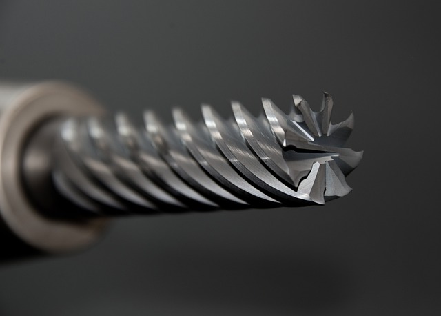
Variable helix and variable pitch end mills are designed specifically to prevent chatter. These tools have helix angles or flute spacing that varies along the length of the cutting edge. A standard end mill has evenly spaced flutes at a constant helix angle. This consistent geometry creates a regular vibration pattern. A variable helix tool disrupts this buildup because each flute hits the material at a slightly different angle and spacing. The vibration energy is spread across a range of frequencies.
Variable helix tools are more expensive than standard end mills but they are worth the cost for any job where chatter is a concern. A single variable helix end mill can eliminate chatter that no amount of speed or feed adjustment can fix. These tools are especially effective in stainless steel, titanium, and other materials prone to chatter.
Fewer Flutes and Roughing End Mills
Fewer flutes can also help because they reduce the tooth pass frequency. A 2-flute end mill running at 10,000 RPM has a tooth pass frequency of 20,000 cycles per minute. A 4-flute end mill at the same speed has 40,000 cycles per minute. The lower frequency may avoid the system resonance. Try switching from a 4-flute to a 2-flute or 3-flute end mill.
Roughing end mills with serrated cutting edges break up the cutting forces and prevent harmonic buildup. The serrated edge creates multiple small chips instead of one continuous chip which disrupts the vibration pattern.
For turning operations use a tool with a smaller nose radius. A smaller nose radius reduces the cutting pressure. Switch from a 1/32 inch nose radius to a 1/64 inch radius insert.
Step 5: Improve Workholding
Support the Workpiece Fully
Workpiece vibration is a common cause of chatter especially on thin-walled parts. Ensure the workpiece is fully supported. Use additional clamps or supports near the cutting area. Add soft jaws or custom fixtures that support thin sections.
For thin-walled parts consider filling the cavity with wax, low-melt alloy, or a vibration damping compound. These materials absorb vibration and prevent the wall from flexing during the cut. This technique is commonly used for aerospace parts with thin walls.
Vacuum Workholding
Vacuum workholding provides excellent support for flat thin parts that are prone to vibration. The vacuum pulls the entire surface of the part flat against the table which prevents the part from flexing during cutting. This is much more effective than clamping the edges because the support is distributed across the entire surface. Use a vacuum table or vacuum pods for parts that are prone to chatter.
Step 6: Use Adaptive Toolpaths
Constant Engagement Toolpaths
High-efficiency milling toolpaths also called adaptive or trochoidal toolpaths maintain a constant radial engagement throughout the cut. This prevents the sudden increases in cutting force that occur when a conventional toolpath enters a corner. The constant engagement keeps cutting forces stable and reduces the likelihood of chatter.
Adaptive toolpaths use a smaller radial engagement typically 5 to 15 percent of the tool diameter with a deeper axial engagement. The light radial load reduces deflection while the deep axial engagement maintains productivity. These toolpaths take longer to calculate in CAM but the machining time is usually shorter because you can run higher feed rates.
Setup for Adaptive Toolpaths
The ideal radial engagement for adaptive toolpaths is typically 5 to 15 percent of the tool diameter. This light radial engagement keeps cutting forces low and prevents deflection. The axial depth can be increased to 2 to 3 times the tool diameter to maintain material removal rates. This combination of light radial and deep axial cutting is the opposite of conventional roughing but it produces better stability and longer tool life in most materials.
If your CAM software supports adaptive toolpaths use them for all roughing operations. The improvement in stability and tool life is dramatic compared to conventional roughing paths. Many CAM programs including Fusion 360 offer adaptive clearing as a standard toolpath strategy.
Step 7: Verify Machine Condition
Check Spindle and Bearings
If you have tried all the above fixes and still have chatter the machine itself may be the problem. Check the spindle runout with a dial indicator. Runout at the tool tip should be under 0.0005 inches. Higher runout causes uneven cutting loads that can trigger chatter.
Check the spindle bearings for wear. Worn bearings have excessive play that allows the spindle to vibrate during cutting. Listen for grinding or whining sounds from the spindle at different RPM ranges. If the bearings are worn they need to be replaced.
Check Machine Setup and Placement
Check the machine leveling and anchoring. A machine that is not level or not bolted down securely transmits vibration through the floor. Check that all leveling screws are tight. Machines on vibration isolation pads are less susceptible to external vibration sources.
Check the guideways and ball screws for signs of wear. Loose guideways allow the machine axes to move under cutting loads which creates vibration. Adjust or replace worn components as needed. On hobby machines with V-wheels check that the wheel eccentric nuts are properly adjusted. Loose V-wheels are a common source of chatter on these machines.
Machine placement also affects chatter. A machine sitting on an uneven floor or near heavy equipment will be more prone to chatter. Use vibration isolation pads under the machine feet. For hobby machines a concrete floor is better than a wooden floor because concrete does not flex under load.
Chatter Troubleshooting Summary
Quick Reference Table
| Step | Fix to Try | Easiest First | Best For |
|---|---|---|---|
| 1 | Reduce tool stickout | ✅ | Most chatter situations |
| 2 | Adjust spindle speed ±5-10% | ✅ | Resonance chatter |
| 3 | Increase feed rate or reduce radial DOC | ✅ | Light chipload chatter |
| 4 | Switch to variable helix or fewer flutes | ❌ | Persistent chatter |
| 5 | Improve workholding with more support | ❌ | Thin-walled parts |
| 6 | Use adaptive toolpaths | ❌ | Roughing operations |
| 7 | Check machine condition and setup | ❌ | Machine-related chatter |
Try steps 1 through 3 first — they are free and quick. Steps 4 through 7 require tool purchases or machine maintenance but solve tougher cases.
Test Program for Chatter Diagnosis
Run this program at different spindle speeds to identify the resonant frequency of your tool setup:
; Chatter diagnosis test
; Run at: 8000, 9000, 10000, 11000 RPM
; Listen for chatter at each speed
G90 G94 G17 G54
G21
M03 S8000        ; Change S value each run
G00 X0 Y0 Z5
G01 Z-0.5 F200   ; Light cut
G01 X50 F400     ; Listen here
G00 Z5
M05
M30
If the cut sounds smooth at 9,000 RPM but chatters at 10,000 RPM, you have identified the resonant frequency. Set your spindle speed to avoid that range during production.
For more troubleshooting guides see our CNC Troubleshooting Guide and our Common G-Code Mistakes guide.
 CNC Surface Finish Guide: Ra Values, Causes, and How to Achieve Each LevelJune 27, 2026 · Guides
 Thin Wall CNC Machining Guide: Beat Deflection and Chatter on Thin PartsJune 27, 2026 · Guides
 CNC Toolpath Troubleshooting Guide: Fix Bad Cuts and Improve Surface FinishJune 27, 2026 · Guides