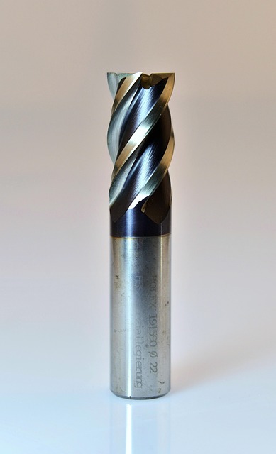
Every CNC machinist has stood over a machine looking at a part that should have been perfect but came out with chatter marks, visible step lines, or burn marks. The first time it happened to me I changed the feed rate, the speed, the tool, and the stepover all at once. The second attempt was worse than the first and I had no idea which change caused the problem.
The key to troubleshooting bad cuts is to change one variable at a time and understand what each variable actually controls. This guide covers the most common toolpath problems, what causes them, and exactly how to fix each one.
The Diagnostic Framework
Before changing any settings, examine the bad cut carefully. The pattern of the defect tells you what is wrong. Even feed lines across the surface indicate a stepover or tool radius issue. Irregular marks that change with each pass indicate vibration or chatter. Burn marks indicate heat problems. Rough sections that appear only in certain areas indicate tool deflection.
The cause of each defect falls into one of five categories: toolpath strategy, speeds and feeds, machine rigidity, tool condition, or workholding. Each category has specific symptoms and fixes. Identifying the category narrows your search.
I learned to keep a cutting log after a job that went through four setup changes before I realized the end mill was chipped. Fifteen minutes with a loupe would have saved two hours of troubleshooting. Look at the tool first. Then look at the part. Then change one variable.
Problem-Symptom-Fix Quick Reference
| Symptom | Most Likely Cause | First Fix to Try |
|---|---|---|
| Even ridges across surface | Stepover too large | Reduce stepover by 50% |
| Irregular chatter marks | Tool deflection or rigidity | Reduce depth of cut, shorten tool stickout |
| Burn marks | Excessive heat | Reduce RPM or increase feed |
| Rough section in one area only | Tool deflection in heavy cut | Reduce radial engagement |
| White or smeared surface | Rubbing instead of cutting | Increase feed to proper chip load |
| Steps at toolpath transitions | Acceleration or backlash | Check machine tuning, add finishing pass |
| Fuzzy surface in wood | Dull tool or high RPM | Replace tool, reduce RPM |
| Gouge in corner | Climb vs conventional conflict | Check lead-in/lead-out strategy |
| Lines at Z-level changes | Stepdown too large finishing pass | Reduce finishing stepdown |
Chatter and Vibration Marks
Chatter appears as visible wavy lines on the machined surface. The marks are usually evenly spaced and follow the direction of cut. Chatter is caused by harmonic vibration between the tool, the workpiece, and the machine.
The most effective fix is to reduce tool overhang. Every inch of tool stickout beyond the collet reduces rigidity by a factor of three. If your tool is sticking out 2 inches from the holder and you can reduce it to 1.5 inches, the rigidity improvement is significant.
Reducing radial engagement also helps. Chatter happens when the cutting forces exceed the rigidity of the system. Taking a lighter cut in the radial direction reduces cutting forces without affecting the surface finish as much as reducing axial depth.
Increasing feed rate slightly can break the harmonic frequency that causes chatter. If you are running at 20 inches per minute, try 25 or 30. The change in cutting force frequency can shift the vibration away from the machine’s natural frequency.
Using a variable flute pitch end mill disrupts harmonic vibrations. Tools with uneven flute spacing are designed specifically for chatter reduction. If you routinely cut materials that chatter, these tools are worth the premium.
Shortening the tool is more effective than any other change. A tool sticking out 1 inch from the holder can take twice the depth of cut as the same tool sticking out 2 inches. If you have chatter and cannot shorten the tool, reduce the depth of cut until the chatter stops, then work up from there.
Check the tool holder runout. A holder with excessive runout causes uneven chip loads between flutes. One flute does most of the cutting while the others barely touch. This unbalanced cutting produces vibration even when all other parameters are correct. Runout should be under 0.0005 inches for finishing operations.
Climb Milling vs Conventional Milling for Chatter
Climb milling generally produces better surface finish than conventional milling. In climb milling the cutting edge enters the material at maximum chip thickness and exits at zero. This reduces rubbing and heat generation.
However conventional milling can reduce chatter in certain situations. When the machine has backlash or the setup lacks rigidity, conventional milling applies cutting forces in a direction that pulls the workpiece into the table rather than lifting it. This can stabilize the cut.
If you have chatter in climb milling, try conventional milling for the finishing pass. If the chatter goes away, the issue is related to machine rigidity or workholding rather than toolpath settings. A roughing pass in climb and a finishing pass in conventional is a valid strategy for difficult materials.
Poor Surface Finish from Stepover
Visible ridges across the machined surface at regular intervals indicate a stepover problem. The ridges are the scallop left between adjacent tool passes. Every machining operation leaves scallops. The goal is to make them small enough that they are within your surface finish tolerance.
Stepover is the distance between adjacent toolpaths. A smaller stepover leaves smaller scallops but increases machining time. The relationship is not linear. Reducing stepover by half doubles the number of passes. But the scallop height reduction follows a square relationship.
For a ball end mill, scallop height equals the stepover squared divided by eight times the tool radius. A 0.020 inch stepover with a 1/4 inch ball mill produces a scallop of about 0.0004 inches. Increasing stepover to 0.040 inches produces a scallop of 0.0016 inches which is four times higher.
For a flat end mill, the scallop is determined by the corner radius. Tools with a corner radius produce smaller scallops than sharp square tools at the same stepover. A 0.030 inch corner radius on a 1/2 inch end mill reduces scallop height by 60 percent compared to a sharp corner.
Recommended Stepover Values
| Operation | Tool Type | Stepover (percent of diameter) |
|---|---|---|
| Roughing | Square end mill | 40-50% |
| Semi-finish | Square end mill | 15-25% |
| Finish (wood) | Ball end mill | 8-10% |
| Finish (metal) | Ball end mill | 4-8% |
| Finish (precision metal) | Ball end mill | 2-4% |
| Finish flat surface | Square with corner radius | 10-15% |
If you need better surface finish and cannot reduce stepover because of time constraints, use a larger tool. A 1/2 inch ball mill produces a scallop height one quarter of a 1/4 inch ball mill at the same stepover. The larger tool removes material faster while producing a better finish.
Burn Marks and Heat Damage
Burn marks appear as discolored areas on the machined surface. The material has been overheated to the point of oxidation or melting. Burn marks are most common on aluminum, plastics, and wood.
The cause is almost always too much heat at the cutting edge. Heat is generated by friction between the tool and the workpiece. The two variables that control heat are cutting speed and chip load.
Reduce spindle RPM first. Cutting speed is the primary driver of heat generation. If the spindle is running too fast, the cutting edge rubs against the material instead of cutting cleanly. Reducing RPM by 20 percent often eliminates burn marks without affecting cutting performance.
Increase feed rate to maintain chip load. When you reduce RPM, chip load per tooth increases at the same feed rate. This is actually beneficial because a thicker chip carries more heat away from the cutting edge. The chip acts as a heat sink.
A common mistake is reducing both RPM and feed together. This keeps the chip load constant but reduces your material removal rate. Instead, reduce RPM and hold feed rate constant. The chip gets thicker which carries more heat away and you maintain your cutting speed.
Use coolant or air blast to remove heat. Flood coolant is the most effective but minimum quantity lubrication or compressed air also helps. Any cooling method is better than none. The goal is to remove heat from the cutting zone before it transfers to the workpiece.
For plastics, the issue is often the material melting and re-solidifying on the cutting edge. A single-flute or two-flute tool with a polished flute surface reduces the friction that causes melting. Running an air blast across the cutting zone also helps clear melted material.
Tool Deflection Issues
Tool deflection produces tapered walls, oversize features, and poor surface finish in specific areas of the part. The tool bends under cutting pressure and the actual cut position differs from the programmed position.
Deflection is determined by tool diameter, stickout length, and cutting forces. A 1/8 inch end mill sticking out 1 inch deflects eight times more than the same tool sticking out 0.5 inches. The relationship is cubic. Doubling stickout increases deflection by eight times.
The fix for deflection is to use the shortest possible tool, the largest possible tool diameter, and the lightest possible radial engagement. If you need a long tool to reach a deep feature, take multiple light passes rather than one heavy pass.
Roughing with a larger tool and finishing with a smaller tool is the standard strategy. The large tool handles material removal where deflection does not matter. The small tool takes a light finishing pass where the cutting forces are low enough that deflection stays within tolerance.
Maximum Deflection Guidelines
| Operation | Max Allowable Deflection |
|---|---|
| Roughing | 0.003-0.005 inches |
| Semi-finish | 0.001-0.002 inches |
| Finishing (general) | 0.0005-0.001 inches |
| Finishing (precision) | Under 0.0005 inches |
If your finishing pass shows deflection, reduce radial engagement rather than axial depth. Radial engagement has a directly proportional effect on cutting forces. Halving the radial engagement halves the cutting force and the deflection.
Toolpath Strategy Problems
The CAM toolpath strategy determines how the tool engages with the material. Different strategies produce different cutting force patterns and surface finishes.
Trochoidal vs Conventional Toolpaths
Trochoidal toolpaths use a small radial engagement with high axial depth and high feed rate. The tool moves in a looping pattern that distributes wear across the entire cutting edge. Trochoidal paths reduce cutting forces, eliminate vibration, and allow higher material removal rates.
Conventional toolpaths use full-width slotting or heavy radial engagement. These produce higher cutting forces and more deflection. For rigid machines and stable materials, conventional paths are faster and simpler. For machines with limited rigidity, trochoidal paths produce better results.
Lead-In and Lead-Out
The entry of the tool into the material is the most demanding part of any cut. A poor lead-in causes the tool to slam into the material which produces a mark on the surface and can chip the cutting edge.
Ramp entry is the safest method for most operations. The tool enters the material at a shallow angle rather than plunging directly. A ramp angle of 1 to 3 degrees provides a smooth entry with minimal cutting force spike.
Helical entry is better for large cutouts where the tool must enter from above the material. The tool moves in a spiral downward which distributes the entry load across a large area. Helical entry is standard for pocket milling.
Avoid plunging directly into the material unless the tool is designed for plunge cutting. Most end mills have a center that does not cut. Plunging forces the center of the tool into the material which pushes metal rather than cutting it. This causes deflection, poor finish, and potential tool breakage.
Finishing Pass Strategy
A dedicated finishing pass improves surface finish significantly. The finishing pass removes a small amount of material typically 0.005 to 0.020 inches radially. The light cut produces low cutting forces which minimizes deflection and vibration.
The finishing pass must remove enough material to establish a clean cut. A pass that is too light, under 0.003 inches, can cause rubbing instead of cutting. The tool pushes against the material without forming a proper chip. This produces a burnished surface that looks shiny but has poor dimensional accuracy.
Run the finishing pass in the same direction as the semi-finish pass. Changing direction between passes can cause the tool to engage with a variable chip load which produces inconsistent surface finish.
Machine and Controller Issues
Sometimes the problem is not the toolpath settings but the machine itself. Backlash, loose components, and controller tuning all affect cut quality.
Backlash causes visible steps at direction changes. When the machine reverses direction, the screw must take up the slack before the axis starts moving. The result is a small flat or step at the reversal point. On a pocket wall, backlash appears as a step on one side only.
Check backlash by mounting a dial indicator against the table and moving the axis 0.001 inches in each direction. The difference between the commanded position and the actual position is the backlash. Most hobby machines have 0.001 to 0.003 inches of backlash.
Backlash can be compensated in software. Most CNC controllers including GRBL, Mach4, and LinuxCNC have backlash compensation settings. Enter the measured backlash value and the controller adds the compensation automatically.
Loose axis couplers produce irregular marks that do not follow a consistent pattern. The coupler between the stepper motor and the ball screw can slip under load. Tighten all couplers and check for set screw marks that indicate slipping.
Acceleration settings affect surface finish at corners. If the machine decelerates too quickly into a corner and accelerates too quickly out, the tool lingers at the corner and cuts a deeper divot. Reducing acceleration by 25 to 50 percent improves corner finish significantly.
Step-by-Step Troubleshooting Flow
When you see a bad cut, follow this sequence rather than guessing at the cause.
First, inspect the tool under magnification. A chipped or worn cutting edge produces poor surface finish regardless of settings. If the tool is damaged, replace it and run the same cut again. This solves about 30 percent of surface finish problems.
Second, check the tool holder runout. Mount a dial indicator on the tool shank near the collet and rotate the spindle by hand. Runout over 0.001 inches causes uneven cutting. Clean the collet and reseat the tool. If runout persists, try a different collet.
Third, verify the speeds and feeds. Use a chip load calculator to confirm that the feed rate produces the recommended chip thickness for your tool diameter and material. Most surface finish problems trace back to incorrect chip load.
Fourth, check tram and alignment. A head that is out of tram by 0.005 inches produces visible surface defects. See our [How to Tram a CNC Spindle](
G90 G54 G00 X0 Y0
G01 Z-0.1 F10
G01 X1.0 F20
M30
/posts/how-to-tram-a-cnc-spindle/) guide for the full procedure.
Fifth, evaluate the toolpath strategy. Try a different toolpath pattern like parallel instead of offset, or climb instead of conventional. The change in cutting force direction can eliminate problems that no amount of speed tuning can fix.
For more information on tool selection for better finishes, see our CNC End Mill Selection Guide. For feeds and speeds calculations, see our Feeds and Speeds Guide.
 CNC Part Finishing and Deburring Guide: Methods, Tools, and Best PracticesJune 27, 2026 · Guides
 Aluminum on a Desktop CNC Router: Can It Be Done? A Realistic GuideJune 27, 2026 · Guides
 Thin Wall CNC Machining Guide: Beat Deflection and Chatter on Thin PartsJune 27, 2026 · Guides
 CNC Machining Aluminum: Complete Guide to Feeds, Speeds, and ToolingJune 26, 2026 · Guides