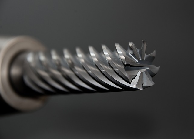
Thin walls are one of the most challenging features to successfully machine on a CNC mill. When the wall thickness drops below 0.050 inches, the wall flexes under cutting pressure. The flex causes the tool to cut more material on some passes than others which produces a wall that is thinner than programmed or has visible deflection marks.
I machined my first thin wall part without any understanding of the challenge involved. The part called for a 0.030 inch wall in 6061 aluminum. I assumed my standard roughing and finishing approach would work fine. I programmed standard roughing and finishing passes. The finished wall came out 0.022 inches thick at the top and only 0.018 inches at the bottom. The deflection was so severe that the cutting tool pushed the wall a full 0.008 inches during each and every pass.
This guide covers the strategies that work for thin wall machining: reducing cutting forces through toolpath choices, supporting the wall with proper workholding, using optimal tool selection, and making multiple light finishing passes. Each strategy addresses a specific aspect of the deflection problem and combining them produces reliable results.
The single most important lesson I learned about thin wall machining is that you cannot cut a thin wall the same way you cut a thick feature. The approach must change completely from the toolpath to the tool selection to the workholding. Attempting to use standard roughing and finishing on a thin wall guarantees deflection and scrap.
What Makes Thin Walls Difficult
The problem with thin walls is that the wall deflects away from the cutting tool during machining. The deflection is proportional to the cutting force and inversely proportional to the wall stiffness. As the wall gets thinner, the stiffness drops dramatically. A wall that is 0.030 inches thick has one-eighth the stiffness of a 0.060 inch wall. This means a 30 percent reduction in wall thickness causes an 87 percent reduction in stiffness.
Wall stiffness depends on three factors. The wall thickness is the primary factor. Stiffness is proportional to the cube of the thickness. Doubling the thickness increases stiffness by eight times. The wall height also matters a lot because a taller wall has more leverage to deflect at the top where the tool engages. The wall material determines the modulus of elasticity. Aluminum with a modulus of 10 million PSI deflects three times more than steel with a modulus of 30 million PSI at the same wall thickness and cutting force.
The deflection causes two distinct problems that compound each other. First, the wall ends up thinner than programmed because the tool pushes the wall away and removes less material on each pass. The top of the wall deflects more than the bottom which produces a tapered wall profile. Second, the wall vibrates during cutting which leaves visible chatter marks on the surface. The vibration gets worse as the wall gets thinner because the natural frequency drops.
The complex interplay between deflection and chatter makes thin wall machining difficult to troubleshoot for beginners. Deflection causes dimensional errors. Chatter causes surface finish problems. Fixing one without addressing the other produces parts that are either the correct thickness with poor finish or good finish with the wrong thickness.
Toolpath Strategies for Thin Walls
The toolpath strategy has the largest impact on thin wall success because it determines how cutting forces are applied to the wall. The right strategy reduces cutting forces and distributes them evenly along the wall height.
Trochoidal Milling
Trochoidal milling uses a small radial engagement with high axial depth and high feed rate. The tool moves in a looping path that keeps the engagement angle constant. The small radial engagement reduces cutting forces by 50 to 80 percent compared to conventional slotting.
For thin walls, trochoidal milling allows roughing without deflecting the wall. The small radial engagement means the cutting force is low enough that the wall does not flex. The high axial depth removes material efficiently despite the light radial cut.
Trochoidal milling requires CAM software that supports the toolpath type. Fusion 360 includes trochoidal toolpaths under the Adaptive Clearing strategy. VCarve does not support trochoidal milling directly but similar results can be achieved with multiple light passes.
Axial Depth Splitting
If your CAM software does not support trochoidal milling, split the axial depth into multiple passes. Instead of cutting the full wall height in one pass, cut it in three or four passes. Each pass removes less material and generates lower cutting forces.
For a 1 inch tall wall, use three passes of 0.333 inches each instead of one pass of 1 inch. The cutting force on each pass is roughly one-third of the single-pass force. The defection is reduced by the same proportion.
The trade-off is longer cycle time. Three passes take three times longer than one pass. For thin walls, the time increase is unavoidable. Attempting to remove the material in one pass causes deflection and scrapped parts.
Climb Milling
Always use climb milling for thin walls. In climb milling, the cutting edge enters the material at maximum chip thickness and exits at zero thickness. The cutting force direction pushes the tool away from the wall which reduces the engagement angle. In conventional milling, the tool enters the material at zero chip thickness and exits at maximum. The cutting force pulls the tool into the wall which increases the engagement and deflection.
The difference between climb and conventional milling is significant for thin walls. Switching from conventional to climb milling can reduce wall deflection by 30 to 50 percent. The reduction in wall deflection is largest on the first finishing pass where the majority of the remaining material is actually removed.
Stepover Reduction
Reduce the radial stepover for thin wall finishing passes. A standard finishing stepover of 0.010 inches may be too aggressive for a wall that is 0.030 inches thick. The cutting force at 0.010 inch stepover is enough to push the wall beyond the acceptable tolerance. Reduce the stepover to 0.003 to 0.005 inches for the final pass.
The light stepover reduces cutting forces to the point where the wall does not deflect measurably. The trade-off is that a very light stepover may cause rubbing instead of cutting. If the chip load per tooth is too low, the tool rubs the wall surface instead of shearing a chip. The rubbing work-hardens aluminum and produces a poor burnished surface finish.
The chip load per tooth must be at least 0.0005 inches for aluminum and 0.001 inches for steel to maintain a cutting action. If the stepover is too small to produce these chip loads at your available feed rate, the tool rubs and the surface finish degrades. Use a tool with more flutes to increase the chip load at the same stepover. A four-flute tool produces double the chip load of a two-flute tool at the same parameters.
Multiple Finishing Passes
Use multiple finishing passes for thin walls instead of one heavy pass. The first finishing pass removes 0.005 to 0.010 inches of material. The second pass removes 0.002 to 0.005 inches. The third pass is a cleanup pass at 0.001 to 0.002 inches.
Each pass reduces the wall thickness and stiffness. The lightest pass comes last when the wall is thinnest and most vulnerable to deflection. The sequence allows roughing and finishing without changing tools or parameters between passes.
Program the multiple finishing passes in the CAM software. Each pass is a separate operation with a smaller stock-to-leave value. The operations run sequentially without operator intervention.
Tool Selection
Tool selection is critical for thin wall machining because the tool’s rigidity determines how much it deflects under cutting forces. The tool must be rigid enough to resist deflection but small enough to fit in the feature being machined.
Use the largest tool diameter that can fit in the feature. A 1/2 inch end mill has 16 times the rigidity of a 1/4 inch end mill because rigidity scales with the fourth power of the diameter. If the thin wall is in a deep pocket that limits the tool diameter, use a tool with a reduced neck or extended reach design that maintains rigidity while allowing access.
Use a tool with the shortest possible flute length. The flute length should be just long enough to cut the wall height plus a small clearance. Extra flute length adds flexibility because the tool is unsupported over a longer span. A tool with a 1 inch flute length deflects four times more than a tool with a 0.5 inch flute length at the same cutting force. If you only need to cut a 0.5 inch wall, do not use a tool with 1.5 inch flutes.
Tool Selection Guide for Thin Walls
| Wall Height | Min Tool Diameter | Max Flute Length | Coating |
|---|---|---|---|
| 0.25 in | 1/8 in | 0.4 in | TiAlN |
| 0.50 in | 1/4 in | 0.7 in | TiAlN |
| 0.75 in | 3/8 in | 1.0 in | AlTiN |
| 1.00 in | 1/2 in | 1.3 in | AlTiN |
| 1.50 in | 5/8 in | 1.8 in | AlTiN |
Workholding for Thin Walls
Workholding must support the thin wall from behind to prevent deflection during cutting. Without support, the wall acts like a cantilever beam and deflects away from the cutting tool. The right workholding approach eliminates or minimizes this deflection.
The best support strategy is to leave the wall attached to a thicker base during roughing and cut the base away in a separate finishing operation. The extra material at the base provides rigidity during the heavy roughing cuts. After roughing, the finishing pass removes the base material and the wall is cut to final thickness when it is most vulnerable.
If the wall is part of a pocket that is surrounded by thicker material, machine the pocket with progressively lighter passes. The material surrounding the pocket provides natural support during roughing. The final light finishing pass removes the last few thousandths when the wall is thinnest and most prone to deflection.
Packing material behind the wall provides direct support during machining. Fill the pocket cavity behind the wall with wax, low-temperature metal alloy, epoxy, or machinable plastic. The packing material prevents the wall from deflecting away from the tool by providing a solid backing. After machining, remove the packing material by melting wax or alloy, dissolving epoxy with solvent, or simply knocking out plastic supports.
For production work with multiple parts, invest in a custom fixture that supports the wall from behind. The fixture is machined from aluminum or plastic to match the exact wall contour. The support eliminates deflection and ensures consistent wall thickness across every part in the run. The fixture cost is justified by reduced scrap rates and faster cycle times.
Finishing Sequence for Thin Walls
The sequence of operations matters as much as the toolpath strategy. The correct sequence removes material gradually and supports the wall through each stage.
Rough the pocket or feature with generous stock allowance of 0.020 to 0.030 inches on the thin wall. Use trochoidal milling or light axial depths to minimize cutting forces. Leave enough material to support the wall through the roughing stage.
Semi-finish the wall with a 0.005 to 0.010 inch stock allowance. Use climb milling with a reduced stepover. The semi-finish pass establishes the wall geometry while leaving enough material for the final pass.
Finish the wall with a 0.001 to 0.003 inch stock allowance. Use the lightest possible radial engagement. The finish pass should remove just enough material to achieve the final dimension and surface finish.
Check the wall thickness after the finish pass. If the wall is thinner than specified, reduce the finish stepover on the next part. If the wall is thicker than specified, increase the finish stepover.
Parameter Recommendations
Start with conservative parameters and increase gradually based on test results. The optimal parameters depend on the wall thickness, height, material, and machine rigidity. Writing down the parameters that work helps replicate the results on future jobs.
For aluminum walls under 0.040 inches thick, use a spindle speed of 10,000 to 12,000 RPM, a feed rate of 30 to 50 inches per minute, an axial depth equal to the full wall height, and a radial stepover of 0.003 to 0.005 inches for finishing. Increase the feed rate if the tool rubs instead of cutting. The chip load should be at least 0.0005 inches per tooth.
For steel walls under 0.030 inches thick, use a spindle speed of 3,000 to 5,000 RPM, a feed rate of 10 to 20 inches per minute, an axial depth of 50 to 75 percent of the wall height, and a radial stepover of 0.002 to 0.004 inches. Steel requires lower cutting speeds and lighter cuts than aluminum because the cutting forces are higher for the same chip load.
Always test your parameters on a scrap piece of the exact same material before cutting the actual part. Cut a test wall at the planned thickness and inspect the result for both dimension and surface finish. Adjust the parameters based on the test results before committing to the production part. The entire test procedure takes about 15 minutes and prevents scrapping an expensive finished workpiece.
Thin wall machining is one of the most challenging operations in CNC work but the techniques for success are well-established and repeatable. Use trochoidal or adaptive toolpaths for roughing. Switch to climb milling with reduced stepover for finishing. Support the thin wall with packing material behind it or a custom machined fixture. Use the largest diameter tool that fits with the shortest possible flute length. Divide the finishing into multiple light passes.
The single most common beginner mistake is attempting to remove all the remaining material in one heavy finishing pass. Thin walls need multiple light passes that progressively reduce the stock to the final dimension. Each pass removes less material and the final pass is barely a skin cut. The extra finishing passes add cycle time to the operation but the only real alternative is a major scrapped part that costs more in material and time than the extra passes ever would.
Practice on scrap material before cutting thin walls on production parts whenever possible. The small scrap material cost is much lower than scrapping an expensive workpiece after many hours of machining. Cut test walls at various target thicknesses and carefully measure the actual results with a micrometer. The experience builds valuable intuition for how your specific machine and tooling behave with thin features over a range of operating conditions.
For more information on tool selection, see our [CNC End Mill Selection Guide](
G90 G54 G00 X0 Y0
G01 Z-0.1 F10
G01 X1.0 F20
M30
/posts/cnc-end-mill-selection-guide/) and CNC End Mill Coatings Guide. For feeds and speeds, see our Feeds and Speeds Guide. For troubleshooting surface finish, see our CNC Toolpath Troubleshooting Guide.
 CNC Toolpath Troubleshooting Guide: Fix Bad Cuts and Improve Surface FinishJune 27, 2026 · Guides
 CNC Chatter and Vibration Troubleshooting Guide: Causes and FixesJune 27, 2026 · Guides
 CNC Part Finishing and Deburring Guide: Methods, Tools, and Best PracticesJune 27, 2026 · Guides
 CNC Surface Finish Guide: Ra Values, Causes, and How to Achieve Each LevelJune 27, 2026 · Guides